Method for the predictive closed-loop control of a linear drive or of a linear compressor and linear drive or linear compressor subject to predictive closed-loop control

a closed-loop control and linear compressor technology, applied in the direction of positive-displacement liquid engine control, motor/generator/converter stopper, dynamo-electric converter control, etc., can solve the problem of linear compressor functional incompetence, complicated fine-tuning of compressors, and damage to compressor pistons or valve plates. , to achieve the effect of precise reversal point position, improved efficiency during operation, and improved efficiency

Active Publication Date: 2012-02-28
EMBRACO IND DE COMPRESSORES E SOLUCOES EM REFRIGERACAO LTDA +1
View PDF12 Cites 2 Cited by
  • Summary
  • Abstract
  • Description
  • Claims
  • Application Information

AI Technical Summary

Benefits of technology

[0047]Advantageously, at least one of the recording means for recording the points in time at which the rotor and / or the compressor piston move past a position during their forward movement is arranged in a position at between 20% and 10%, in particular between 17% and 12%, of the gap between the two reversal points in front of a reversal point. The nearer the recording means is arranged to the reversal points, the more precise the position of the reversal point can be established. If the recording means is too near to a reversal point, however, then the movement of the rotor or the compressor piston during the transient effect and the closed-loop control can no longer take hold soon enough to avert a collision. It has proven advantageous to arrange the recording means in particular at 15% of the gap between the two reversal points in front of a reversal point, in order to obtain a balance between the two aspects.
[0048]The method according to the invention for cooling goods and / or for compressing a fluid uses the device according to the invention and / or the closed-loop control method according to the invention. Because of the increased efficiency in closed-loop control of the linear drive or the linear compressor, and the accompanying increased degree of efficiency during operation, the method for cooling goods or for compressing a fluid can be carried out particularly simply and efficiently, so that the goods can be cooled to a high degree of efficiency swiftly, reliably and in an energy-saving manner, or rather the fluid can be compressed to a high degree of efficiency swiftly, reliably and in an energy-saving manner.

Problems solved by technology

Here however, a collision of the compressor piston with the valve plate must be avoided since a collision of the compressor piston can lead to damage to the compressor piston or to a valve plate.
Moreover, a piston rod for the power transmission between compressor piston and linear drive can break, which likewise leads to functional incompetency of the linear compressor.
Fine-tuning the compressor is complicated however, and deceleration with the linear drive reduces its degree of efficiency.

Method used


Image

  • Method for the predictive closed-loop control of a linear drive or of a linear compressor and linear drive or linear compressor subject to predictive closed-loop control
  • Method for the predictive closed-loop control of a linear drive or of a linear compressor and linear drive or linear compressor subject to predictive closed-loop control
  • Method for the predictive closed-loop control of a linear drive or of a linear compressor and linear drive or linear compressor subject to predictive closed-loop control

Examples


Embodiment Construction

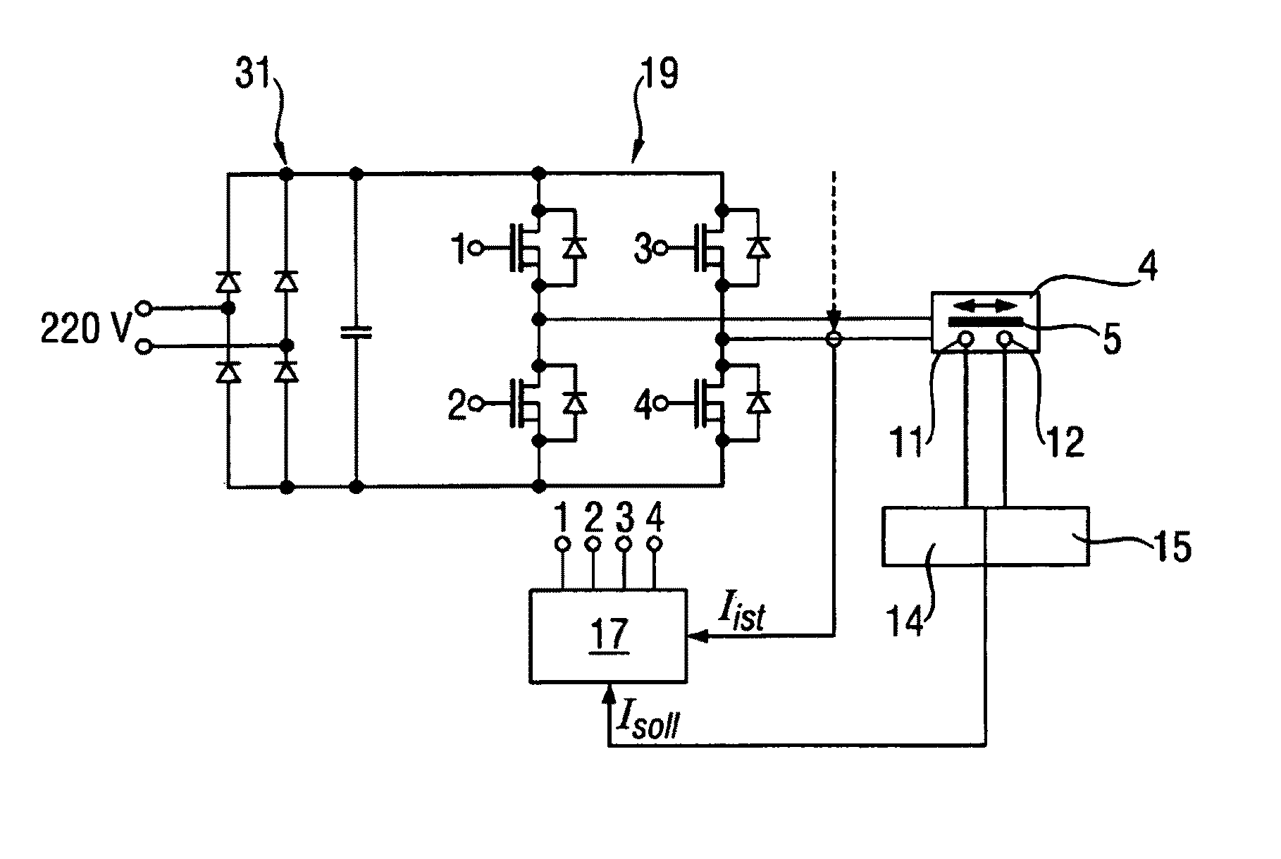
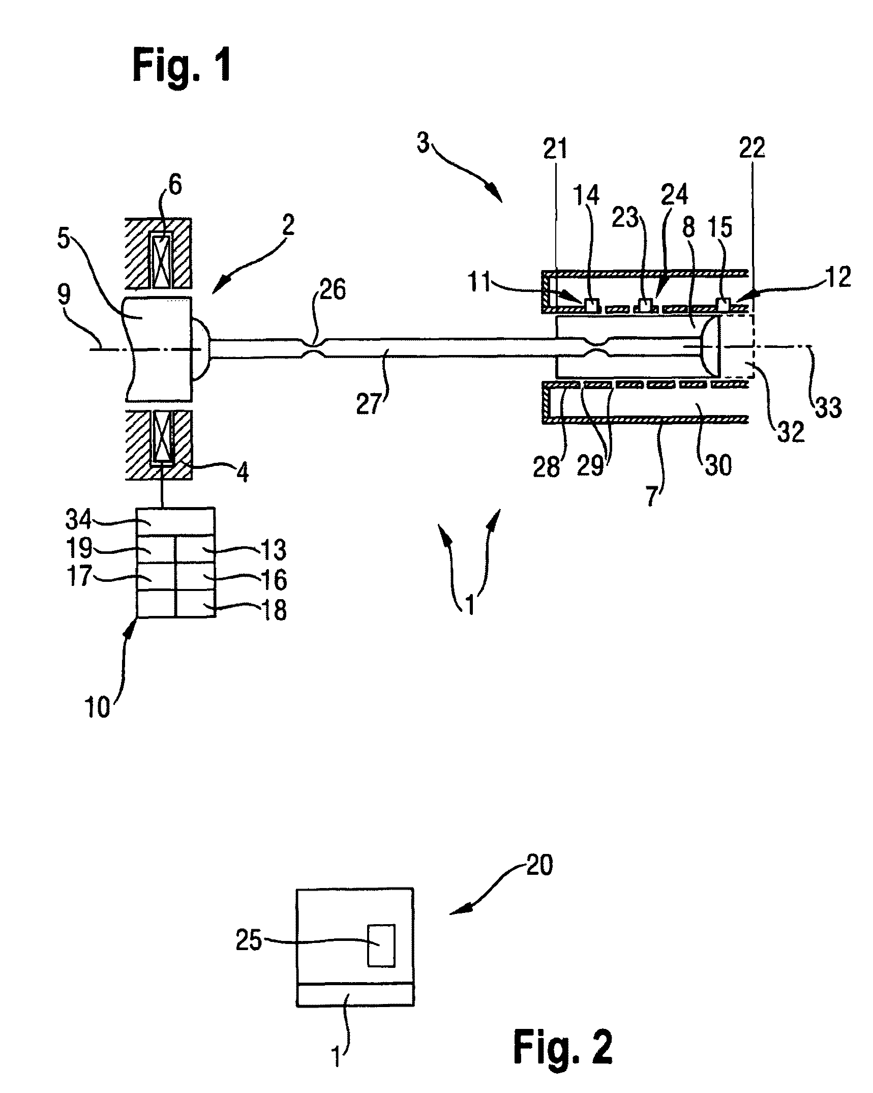
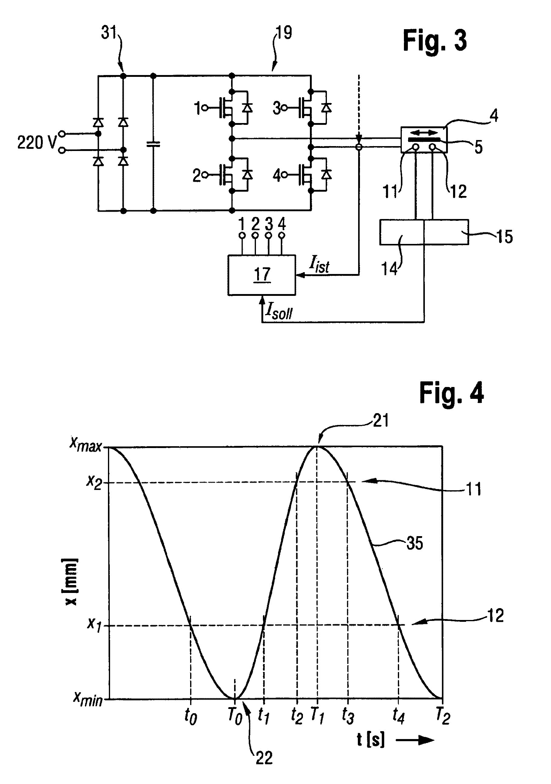
[0059]FIG. 1 shows a device 1 according to the invention in cross section with a linear drive 2 which drives a linear compressor 3 for compressing a gaseous fluid 32. The fluid 32 can be a coolant which is fed into a condensation level (not shown). The linear drive 2 comprises a stator 4, in which a rotor 5 can be moved to and fro along a drive axis 9. The rotor has magnets (not shown) which are moved with the help of a drive coil 6.

[0060]The linear drive 2 is connected via a piston rod 27 to a compressor piston 8 which can be moved to and fro along a piston axis 33 in a piston housing 7. The piston rod 27 has couplings 26 formed as narrow points, which serve to prevent the compressor piston 8 from tilting. The couplings 26 can absorb deflections acting at right angles in respect of the piston rod 27.

[0061]With the help of a housing wall 28 which has openings 29, the compressor piston 8 is mounted on the side, i.e. in a direction at right angles to the piston axis 33, by a fluid pro...


PUM


Abstract

A method for closed-loop control of a linear drive including a stator, a rotor configured for reciprocating movement along a drive axis therein, and a drive coil through which coil current flows, in particular for a linear compressor including a piston housing and a compressor piston configured for reciprocating movement along a piston axis therein, and driven by the linear drive wherein the coil current is subject to closed-loop control, the method including the steps of determining a target coil current and applying an actual coil current wherein the actual coil current and the target coil current are substantially the same value.

Description

BACKGROUND OF THE INVENTION[0001]The invention relates to a method for the control of a linear drive which has a stator, a rotor which is capable of moving to and fro along a driving axis therein and a drive coil through which a coil current flows, in particular for a linear compressor which has a piston housing and a compressor piston which is capable of moving to and fro along a piston axis therein and is driven by a linear drive, as well as a device comprising a linear drive which has a stator, a rotor which is capable of moving to and fro along a drive axis therein, a drive coil through which a coil current flows and a means for the control of a coil current, in particular for a linear compressor which has the linear drive, a piston housing and a compressor piston which is capable of moving to and fro along a piston axis and can be driven by the linear drive, as well as a method for cooling goods and / or for compressing a fluid.[0002]In a linear compressor, the compressor piston ...

Claims


Application Information

Patent Timeline
Patent Type & Authority Patents(United States)
IPC IPC(8): H02P1/00
CPCH02P25/027H02P25/06H02P25/032H02P25/062
Inventor REINSCHKE, JOHANNES
Owner EMBRACO IND DE COMPRESSORES E SOLUCOES EM REFRIGERACAO LTDA
Why Eureka
Try Eureka