Zoom lens system and optical apparatus using the same

a technology of zoom lens and optical apparatus, applied in the field of zoom lens system and optical apparatus, can solve problems such as severe deterioration of resolution

Active Publication Date: 2012-02-28
NIKON CORP
View PDF26 Cites 2 Cited by
  • Summary
  • Abstract
  • Description
  • Claims
  • Application Information

AI Technical Summary

Benefits of technology

[0035]According to a fourth aspect of the present invention, there is provided a method for varying a focal length of a zoom lens system that consists of, in order from an object, a first lens group having negative refractive power and a second lens group having positive refractive power, the first lens group consisting of, in order from the object, a first lens having negative refractive power and a second lens having positive refractive power, and the second lens group consisting of, in order from the object, a third lens having positive refractive power, a fourth lend having negative refractive power, and a fifth lens having positive refractive power, and at least a portion of the second lens group being shifted in a direction substantially perpendicular to an optical axis, the method comprising a step of: decreasing a distance between the first lens group and the second lens group upon varying a state of lens group positions from a wide-angle end state to a telephoto end state.
[0038]The present invention makes it possible to provide a zoom lens system with a vibration reduction function excellently correcting various aberrations with accomplishing to be compact, lightweight, and slim upon being accommodated, and to provide an optical apparatus using the zoom lens system.

Problems solved by technology

Upon taking a picture, a camera shake is a cause of severely deteriorating resolution.

Method used


Image

  • Zoom lens system and optical apparatus using the same
  • Zoom lens system and optical apparatus using the same
  • Zoom lens system and optical apparatus using the same

Examples


example 1

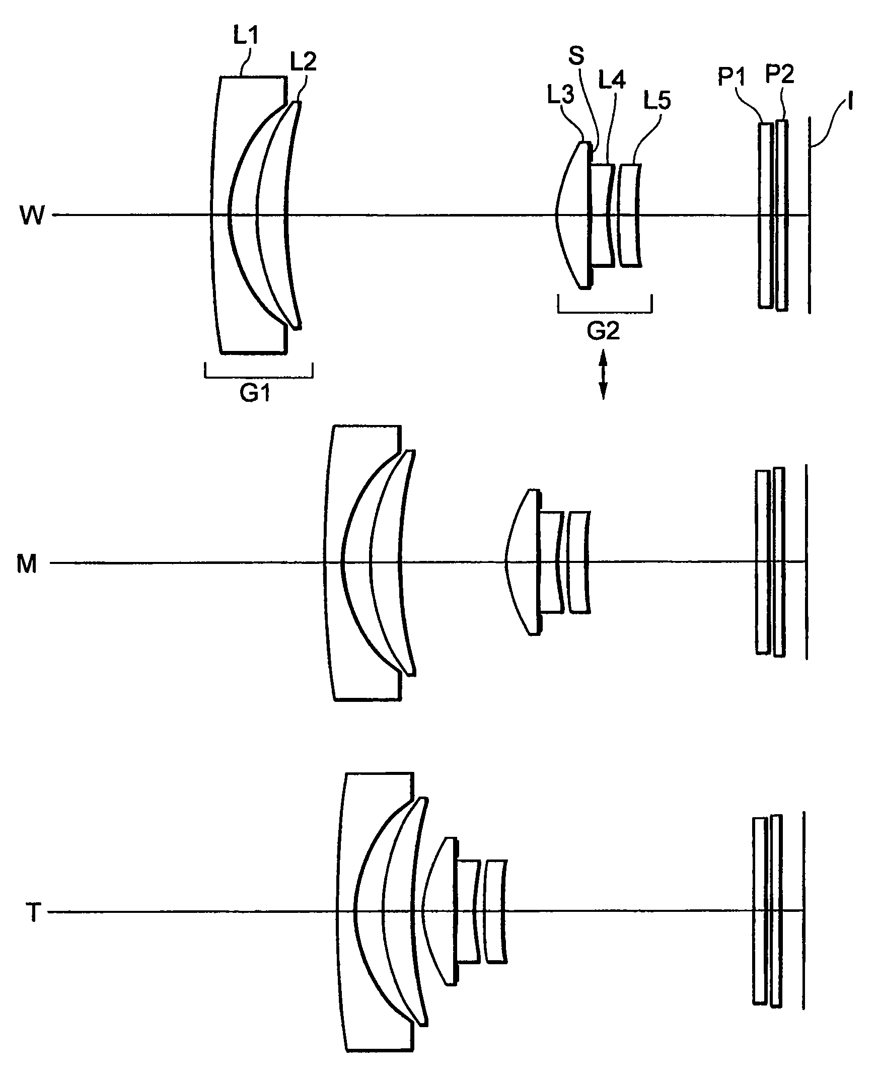
[0117]FIG. 3 is a diagram showing a lens configuration of a zoom lens system according to Example 1 of the present embodiment, in which W denotes a wide-angle end state, M denotes an intermediate focal length state, and T denotes a telephoto end state. Reference symbols used in the following explanations are attached only to a diagram showing the wide-angle end state W, and are omitted in the other states. The same rule is applied to the other Examples.

[0118]In FIG. 3, the zoom lens system according to Example 1 is composed of, in order from an object, a first lens group G1 having negative refractive power, and a second lens group G2 having positive refractive power. When a state of lens group positions varies from a wide-angle end state W to a telephoto end state T, the first lens group G1 and the second lens group G2 are moved along an optical axis such that a distance between the first lens group G1 and the second lens group G2 decreases.

[0119]The first lens group G1 having negat...

example 2

[0136]FIG. 6 is a diagram showing a lens configuration of a zoom lens system according to Example 2 of the present embodiment, in which W denotes a wide-angle end state, M denotes an intermediate focal length state, and T denotes a telephoto end state.

[0137]In FIG. 6, the zoom lens system according to Example 2 is composed of, in order from an object, a first lens group G1 having negative refractive power, and a second lens group G2 having positive refractive power. When a state of lens group positions varies from a wide-angle end state W to a telephoto end state T, the first lens group G1 and the second lens group G2 are moved along an optical axis such that a distance between the first lens group G1 and the second lens group G2 decreases.

[0138]The first lens group G1 having negative refractive power as a whole is composed of two lenses that are, in order from the object, a double concave negative lens L1, and a positive meniscus lens L2 having a convex surface facing the object.

[0...

example 3

[0147]FIG. 9 is a diagram showing a lens configuration of a zoom lens system according to Example 3 of the present embodiment, in which W denotes a wide-angle end state, M denotes an intermediate focal length state, and T denotes a telephoto end state.

[0148]In FIG. 9, the zoom lens system according to Example 3 is composed of, in order from an object, a first lens group G1 having negative refractive power, and a second lens group G2 having positive refractive power. When a state of lens group positions varies from a wide-angle end state W to a telephoto end state T, the first lens group G1 and the second lens group G2 are moved along an optical axis such that a distance between the first lens group G1 and the second lens group G2 decreases.

[0149]The first lens group G1 having negative refractive power as a whole is composed of two lenses that are, in order from the object, a double concave negative lens L1, and a positive meniscus lens L2 having a convex surface facing the object.

[0...


PUM


Abstract

Providing a zoom lens system with a vibration reduction function excellently correcting aberrations with accomplishing compact, lightweight, and slim upon being accommodated, and to provide an optical apparatus using the zoom lens system. The system consists of, in order from an object, a first group having negative power, a second group having positive power. Upon zooming from a wide-angle end to a telephoto end, a distance between the first group and the second group decreases. The first group consists of, in order from the object, a first lens having negative power and a second lens having positive power. The second group consists of, in order from the object, a third lens having positive power, a fourth lens having negative power, and a fifth lens having positive power. An image blur is corrected by shifting the second group as a whole in a direction substantially perpendicular to the optical axis.

Description

[0001]The disclosure of the following priority application is herein incorporated by reference:[0002]Japanese Patent Application No. 2007-036779 filed on Feb. 16, 2007.BACKGROUND OF THE INVENTION[0003]1. Field of the Invention[0004]The present invention relates to a zoom lens system and an optical apparatus using the zoom lens system.[0005]2. Related Background Art[0006]With increasing miniaturizing trend of digital cameras, an optical system loaded thereon has strongly been required to be compact and lightweight to increase portability. With increasing integration of solid-state imaging devices, there has been required a zoom lens system capable of providing high contrast with respect to a higher spatial frequency. There has been proposed a negative-leading zoom lens system suitable for a compact digital camera using such a solid-state imaging device in Japanese Patent Application Laid-Open No. 2006-133755.[0007]Upon taking a picture, a camera shake is a cause of severely deteriora...

Claims


Application Information

Patent Timeline
Patent Type & Authority Patents(United States)
IPC IPC(8): G02B27/64
CPCG02B15/177G02B27/646G02B15/1425
Inventor MURATANI, MAMI
Owner NIKON CORP
Why Eureka
Try Eureka