Collision detecting device

a detection device and collision detection technology, applied in the direction of roofs, bumpers, pedestrian/occupant safety arrangements, etc., can solve the problem of difficulty in accurately determining whether the collision obstacle is a pedestrian, and achieve the effect of accurately determining the collision of an object with a vehicl

Inactive Publication Date: 2012-03-06
DENSO CORP
View PDF18 Cites 21 Cited by
  • Summary
  • Abstract
  • Description
  • Claims
  • Application Information

AI Technical Summary

Benefits of technology

[0005]It is an object of the present disclosure to provide a collision detecting device which can determine collision of an object with a vehicle accurately without being affected by the change of temperature.
[0007]Hereby, a collision detecting device which can determine collision of an object with a vehicle accurately without being affected by the change of temperature can be obtained.
[0009]Hereby, a collision detecting device which can determine collision of an object with a vehicle accurately without being affected by the change of temperature can be obtained.

Problems solved by technology

Therefore, when temperature changes significantly, it is difficult to determine accurately whether the collided obstacle is a pedestrian.

Method used


Image

  • Collision detecting device
  • Collision detecting device
  • Collision detecting device

Examples


first embodiment

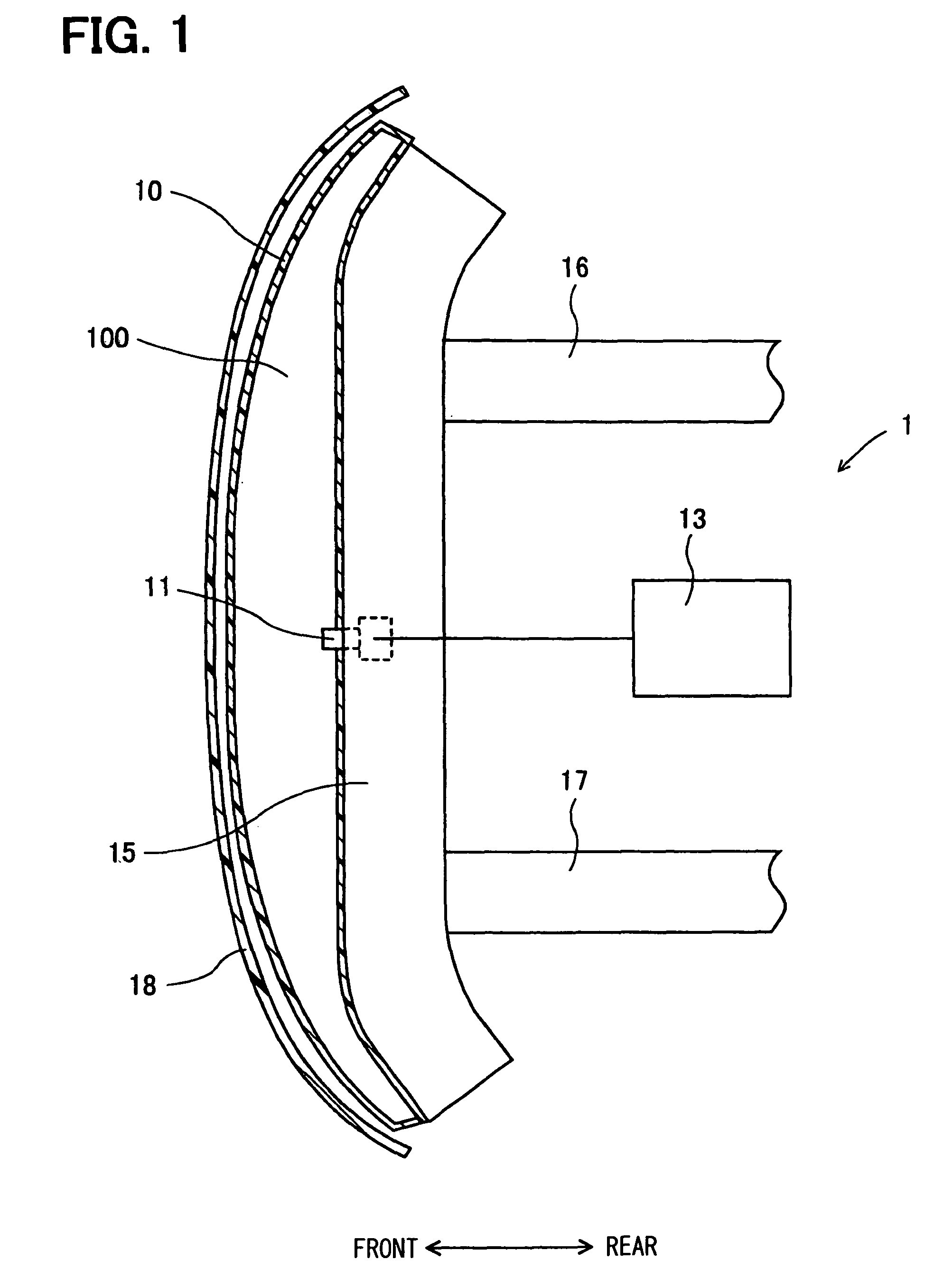
[0019]A structure of a pedestrian collision detecting device is described with reference to FIG. 1 and FIG. 2.

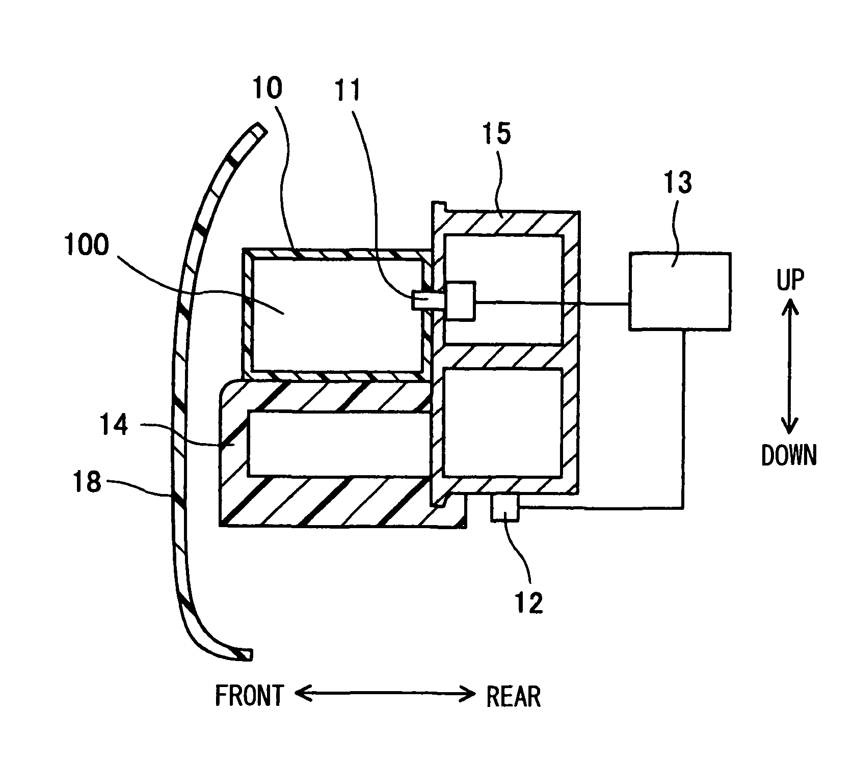
[0020]As shown in FIGS. 1 and 2, a pedestrian collision detecting device 1 (a collision detecting device) includes a chamber member 10, a pressure sensor 11, a temperature sensor 12, a pedestrian collision determination portion 13 (a determination means) and a bumper absorber 14.

[0021]The chamber member 10 is an elongated sack-like member made of such as resin, which has a cross section of a square shape, and constitutes a chamber 100, which is a sealed space or a substantially sealed space. Air is filled in the chamber 100. The chamber member 10 is attached to an upside front surface of a bumper reinforcement 15 extending in a lateral direction of the vehicle, which has a cross section that substantially two squares are attached in line. The bumper reinforcement 15 is attached to front side end portions of a pair of side members 16 and 17, which extends in the front-rear di...

second embodiment

[0035]A pedestrian collision detecting device of a second embodiment is described. The second embodiment is a modification of the first embodiment with respect to the structures of the chamber member and the bumper absorber.

[0036]A structure of the pedestrian collision detecting device is described with reference to FIG. 5. In the second embodiment, a chamber member and a bumper absorber, which have different structures shown in the first embodiment, are described.

[0037]As shown in FIG. 5, a pedestrian collision detecting device 2 (a collision detecting device) includes a chamber member 20, a pressure sensor 21, a temperature sensor 22, a pedestrian collision determination portion 23 (a determination means) and a bumper absorber 24. The chamber member 20 is an elongated sack-like member made of such as resin, which has a cross section of a square shape. The chamber member 20 is attached to a front surface of a bumper reinforcement 25 extending in a lateral direction of the vehicle. ...


PUM


Abstract

A collision detecting device includes a chamber member providing a space, a pressure sensor for detecting a pressure inside the space, a determination means, a bumper absorber for absorbing an impact generated by collision and a temperature sensor for detecting a temperature of the chamber member. Hardness of the chamber member changes with temperature. Thus, the deformation degree of the chamber member is different depending on temperature. However, the determination means corrects the pressure detected by the pressure sensor based on the temperature detected by the temperature sensor, and determines collision based on the corrected pressure. Therefore, a collision detecting device which can determine collision of an object with a vehicle accurately without being affected by the change of temperature can be obtained.

Description

CROSS REFERENCE TO RELATED APPLICATION[0001]This application is based on Japanese Patent Application No. 2007-186217 filed on Jul. 17, 2007, the disclosure of which is incorporated herein by reference.FIELD OF THE INVENTION[0002]The present invention relates to a collision detecting device for detecting collision of a pedestrian or the like with a vehicle.BACKGROUND OF THE INVENTION[0003]The conventional obstacle determination device for vehicles is disclosed in JP-A-2006-117157 corresponding to U.S. 2006 / 0087417 Al as a pedestrian collision detecting device for detecting collision of a pedestrian or the like with a vehicle. The obstacle determination device includes an absorber, a pressure sensor, a velocity sensor and an airbag ECU device. The absorber is a member for absorbing an impact generated by collision of an object with a vehicle. The absorber includes a chamber member and a connection member. The chamber member is attached to a front surface of a bumper reinforcement by t...

Claims


Application Information

Patent Timeline
Patent Type & Authority Patents(United States)
IPC IPC(8): B60R19/48B60R19/03
CPCB60R21/0136B60R19/483
Inventor TANABE, TAKATOSHI
Owner DENSO CORP
Why Eureka
Try Eureka