Method of restoration of a highly saline lake

a restoration method and lake technology, applied in water cleaning, agriculture, chemistry apparatus and processes, etc., can solve the problems of no restoration, no restoration, and corresponding increase in salinity, so as to facilitate optimization and efficiency, facilitate design flexibility, and enhance safety

Active Publication Date: 2012-03-06
C F BEAN
View PDF8 Cites 9 Cited by
  • Summary
  • Abstract
  • Description
  • Claims
  • Application Information

AI Technical Summary

Benefits of technology

[0028]The flexible design of the present invention allows to adjust the remaining total wet surface to the actual remaining inflows, hence to the actual transfers. In view of all uncertainties around the transfers, the flexibility of the design is essential.
[0029]The main construction consists of many hundreds of miles of small low head dikes which is attractive in view of safety (compare to high head dams in seismic areas). Also the type of dike construction (e.g. geotube) will enhance safety. Repetition of elements facilitates optimization and efficiency during the phased implementation.

Problems solved by technology

Under these highly saline conditions the benthic organisms that support the current ecology of the Salton Sea could no longer survive.
If an appropriate Salton Sea restoration plan is not implemented, a substantial portion of the inflow may be diverted permanently from the Salton Sea area such that no restoration would be possible.
The reduced water volume in the Salton Sea will also result in a corresponding increase in salinity.
Without affirmative restoration activities, a number of adverse environmental consequences would result, such as a reduction of the Sea's important habitat values for the Pacific Flyway, increased air pollution, and decreased aesthetics values.
This effort, however, was not completed, primarily due to critical problems identified with all of the alternatives being evaluated, such as excessive costs or environmental impacts.

Method used


Image

  • Method of restoration of a highly saline lake
  • Method of restoration of a highly saline lake
  • Method of restoration of a highly saline lake

Examples


Embodiment Construction

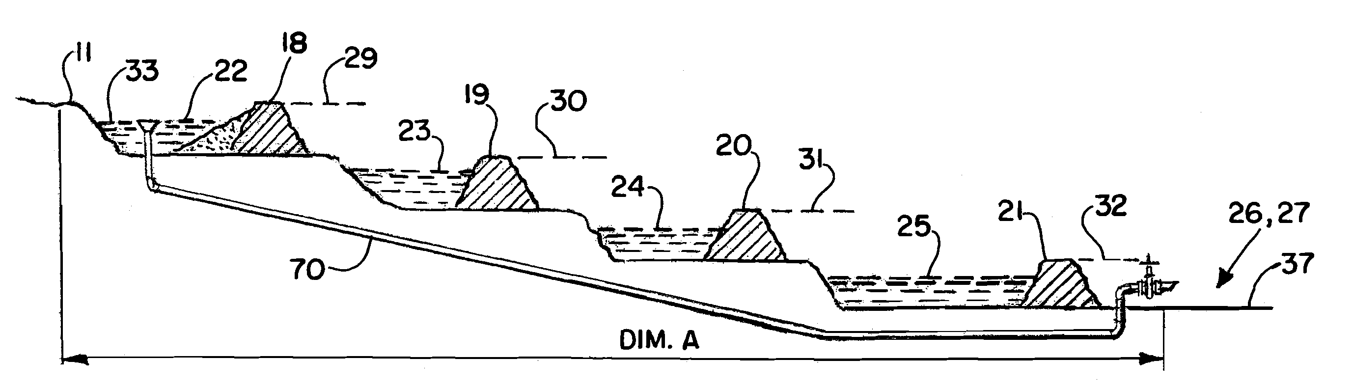
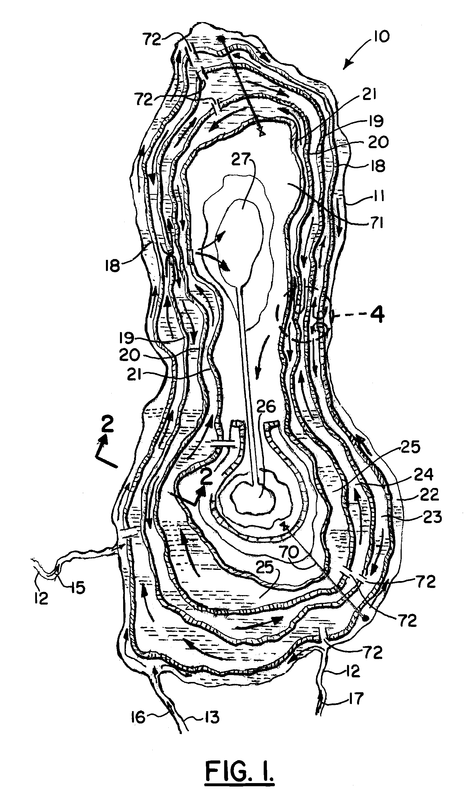
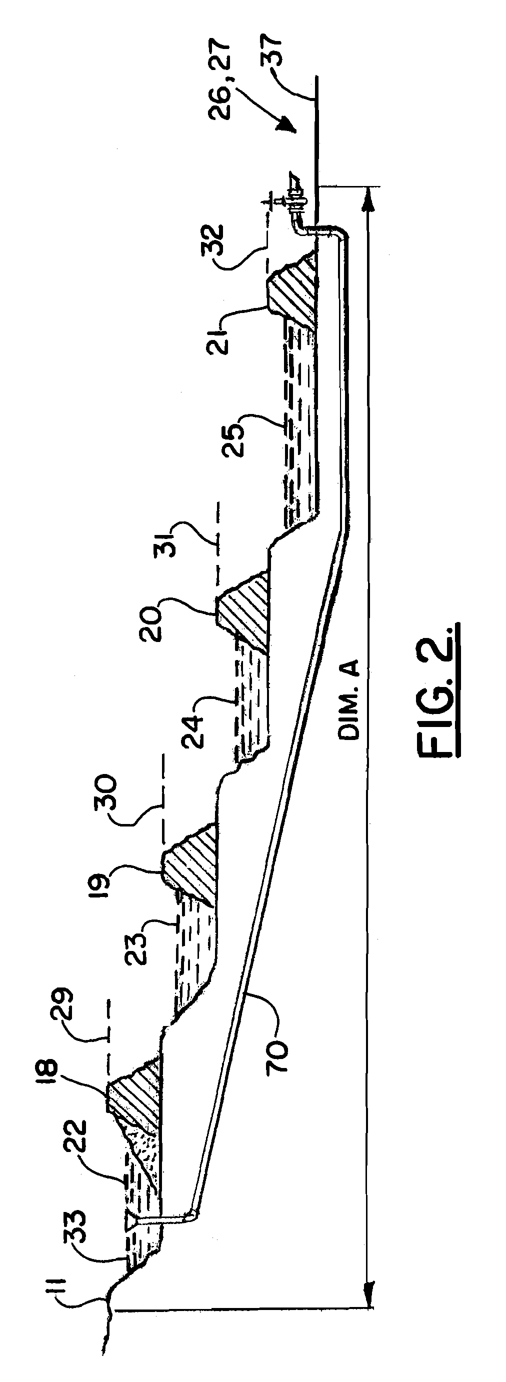
[0038]In FIGS. 1-2, a saline lake 10 is shown that has a shoreline 11. However, it should be understood that FIG. 1 is illustrative and not to scale. The saline lake 10 can be a lake that receives inflow from one or more influent streams 12, 13, 14. The method and apparatus of the present invention can be used to restore an existing saline lake such as the Salton Sea located in Southern California. In FIG. 1, each influent steams 12, 13, 14 is provided with an arrow 15, 16, 17 respectively that indicates the direction of flow.

[0039]The influent streams 12, 13, 14 can be existing rivers. A lake that is receiving an influent stream, influent streams, or an influent flow containing salt can increase in salinity. This problem is compounded if the lake does not have an outflow as is the case with the Salton Sea. If there is no outflow, as water flows from the influent streams 12, 13, 14 into the lake 10, the only way for the water to escape from the lake 10 is by evaporation. Evaporation...


PUM


Abstract

A method of restoring a lake that has a high saline level is disclosed herein. In order to restore the lake, a series of concentric dikes or levees are provided that separate the lake into a plurality of smaller lake sections, each having a water surface. The smaller lake sections include an outer lake section which is next to the periphery of the lake and one or more inner lake sections. Each dike and each smaller lake section water surface have an elevation. Water is flowed from an influent source to the outer lake section and then to each of the inner lake sections. The outer lake section surface has a higher elevation. The inner lake section surfaces have cascading lower surface elevations. At a central area, a breathing brine area is provided that is surrounded by the smaller lake sections to provide an area that can be used to concentrate brine. The smaller lake sections can have differing salinity levels for sustaining diverse marine and plant life.

Description

CROSS-REFERENCE TO RELATED APPLICATIONS[0001]This is a continuation application of U.S. patent application Ser. No. 11 / 379,153, filed Apr. 18, 2006 (issuing as U.S. Pat. No. 7,832,959 on Nov. 16, 2010), which was a non-provisional of U.S. Provisional Patent Application Ser. No. 60 / 672,310, filed Apr. 18, 2005, each of which is hereby incorporated herein by reference.[0002]Priority of each of the above-referenced applications is hereby claimed.STATEMENT REGARDING FEDERALLY SPONSORED RESEARCH OR DEVELOPMENT[0003]Not applicableREFERENCE TO A “MICROFICHE APPENDIX”[0004]Not applicableBACKGROUND OF THE INVENTION[0005]1. Field of the Invention[0006]The present invention relates to restoration of a lake having a high saline content. More particularly, the present invention relates to an improved method of restoring a highly saline lake that utilizes inner and outer dikes or levees (preferably concentrically positioned), elongated smaller lakes formed between the dikes, a central area provid...

Claims


Application Information

Patent Timeline
Patent Type & Authority Patents(United States)
IPC IPC(8): E02B13/00
CPCE02B3/00E02B2201/02Y02A40/22
Inventor GROEN, PIETER VANDE GROOT, JORRIT K.
Owner C F BEAN
Why Eureka
Try Eureka