
Radiopaque markers for implantable prostheses

a radiopaque marker and implantable prosthesis technology, applied in the field of radiopaque markers or discrete radiopaque markers, can solve the problems of not being biocompatible or biostable, compromising structural integrity, etc., and achieve the effect of improving radiopacity and locatability of endoprosthesis

Inactive Publication Date: 2006-08-01
SCHNEIDER (USA) INC
View PDF6 Cites 35 Cited by
  • Summary
  • Abstract
  • Description
  • Claims
  • Application Information

AI Technical Summary

Benefits of technology

[0010]Accordingly, there is a need for retrievable radiopaque markers for use in implantable endoprostheses to improve radiopacity and the locatability of endoprostheses in various medical procedures. Providing temporary radiopacity is especially advantageous for implantable endoprostheses having little or no radiopacity. The markers allow radiographic identification of one or more locations of interest on an implantable endoprosthesis. The locations of interest may include one or more covered or coated regions.
[0014]The temporary retrievable radiopaque marker of the present invention advantageously allows most any implantable endoprosthesis to have temporary radiopacity over a predetermined portion of its structure, and assists with proper positioning and locatability of the implantable endoprosthesis in a body lumen.
[0015]Use of temporary retrievable radiopaque markers on an implantable endoprosthesis is advantageous because the radiopaque property may be present only for a desired time period. Generally, radiopacity is most desirable during placement of the implant. Once the implantable endoprosthesis is implanted, it may be more desirable to image the device with techniques such as ultrasound, magnetic resonance, and endoscopy and avoid further radiation exposure to the patient. Temporary radiopacity may be made by incorporating non-integral, retrievable radiopaque constituents into the implant. Thus, light metals, thin radiopaque metals, polymers, and ceramics may be utilized for a wide range of properties and flexibility in design of the endoprosthesis.
[0025]The elements hydrogen, oxygen, carbon, and nitrogen are commonly found in the body and in polymers, so elements with higher atomic numbers than these should enhance the radiopacity of a polymer implant or marker. Tantalum, zirconium, titanium, barium, bismuth, and iodine are known to be non-toxic in certain concentrations and thus are candidate elements for enhancing radiopacity of a polymer marker in an implant. These elements can be added to the polymer in various loading percentages and the threshhold above which the loading causes unsatisfactory changes in the polymer characteristics can be determined through material and device testing. The elements which can be added in quantities sufficient to enhance radiopacity and maintain an acceptable level of polymer properties and which are biocompatible could be utilized in markers. The biocompatible elements with a range of atomic numbers from about 22 to about 83 and having linear attenuation coefficients in the range from about 5.46 to about 151.53 cm−1 at 50 KeV should provide enough enhancement in radiopacity without excessive thickness being necessary to be useful in markers. These elements would include at least titanium, vanadium, chromium, iron, cobalt, nickel, copper, bromine, zirconium, niobium, molybdenum, silver, iodine, barium, tantalum, tungsten, platinum, gold, and bismuth. The preferred metallic elements for biocompatibility and radiopacity are titanium, zirconium, tantalum, and platinum. The preferred organic elements for biocompatibility and radiopacity are bromine, iodine, barium, and bismuth. Especially preferred elements are tantalum, platinum, barium, and bismuth because of their high atomic numbers and biocompatibility (atomic numbers from about 56 to 83 and linear attenuation coefficients from 49.68 to 149.08). Tantalum and platinum are used as stent components and barium sulfate and bismuth trioxide are used as radiopaque enhancements for polymer catheters.
[0031]The invention also relates to in combination, a discrete radiopaque marker and implantable endoprosthesis. The implantable endoprosthesis has one or more attachment areas and is adapted to be disposed in a body lumen. One or more elongate markers have a proximal end, a distal end, and one or more portions therebetween. The markers have a thickness of from about 20 microns to about 500 microns and include a radiopaque material having a linear attenuation coefficient of from about 5.46 cm−1 at 50 KeV to about 151.53 cm−1 at 50 KeV. The one or more portions of the marker are deformed and permanently disposed about the one or more attachment areas of the endoprosthesis. The markers may be deformed by plastic deformation, elastic deformation, or combinations thereof. The marker may include a twist, knot, crimp, weld, and combinations thereof. The one or more portions may be ductile. The marker may be a spring. The deformation of one or more portions of the marker into an attachment position on the attachment area thereby prevents the marker from releasing from the implantable endoprosthesis.

Problems solved by technology

A disadvantage of some permanent radiopaque markers is that they may compromise structural integrity, may not be biocompatible or biostable, and may be more thrombogenic than the implantable endoprosthesis.

Method used


Image

  • Radiopaque markers for implantable prostheses
  • Radiopaque markers for implantable prostheses
  • Radiopaque markers for implantable prostheses

Examples


example 1

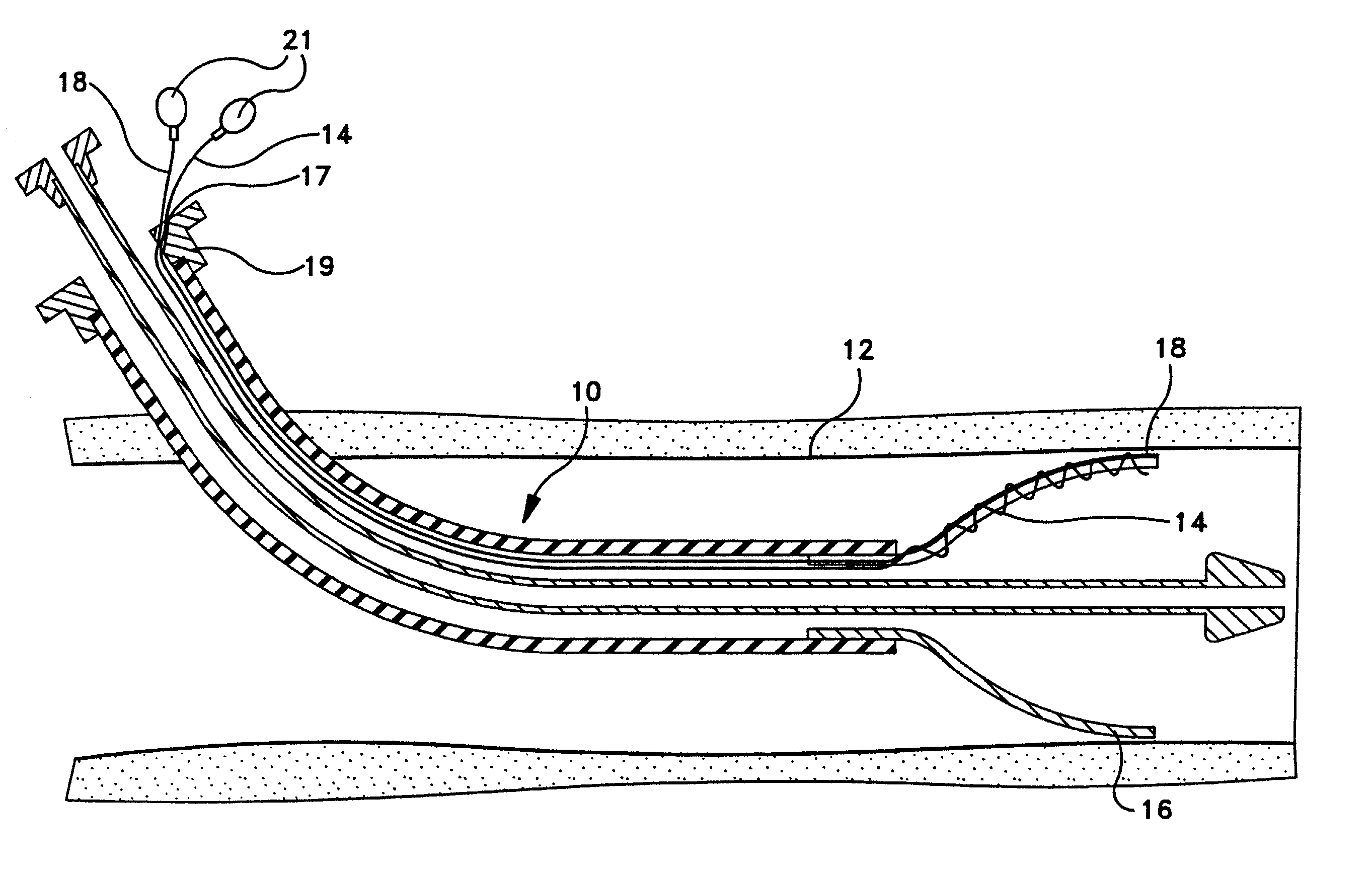
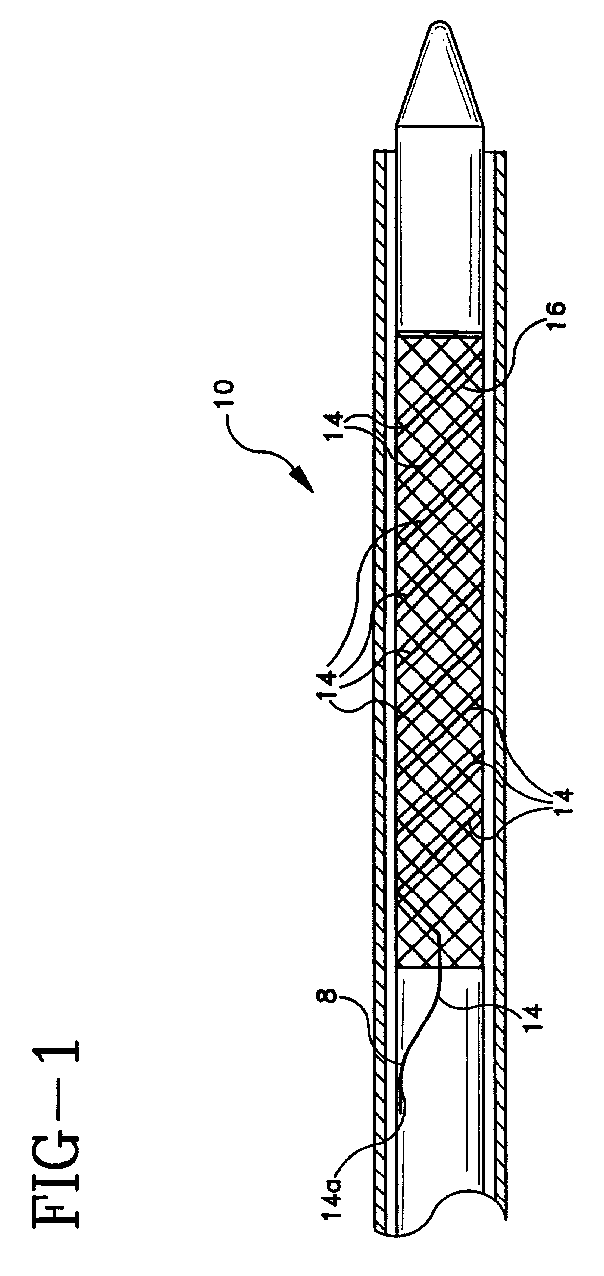
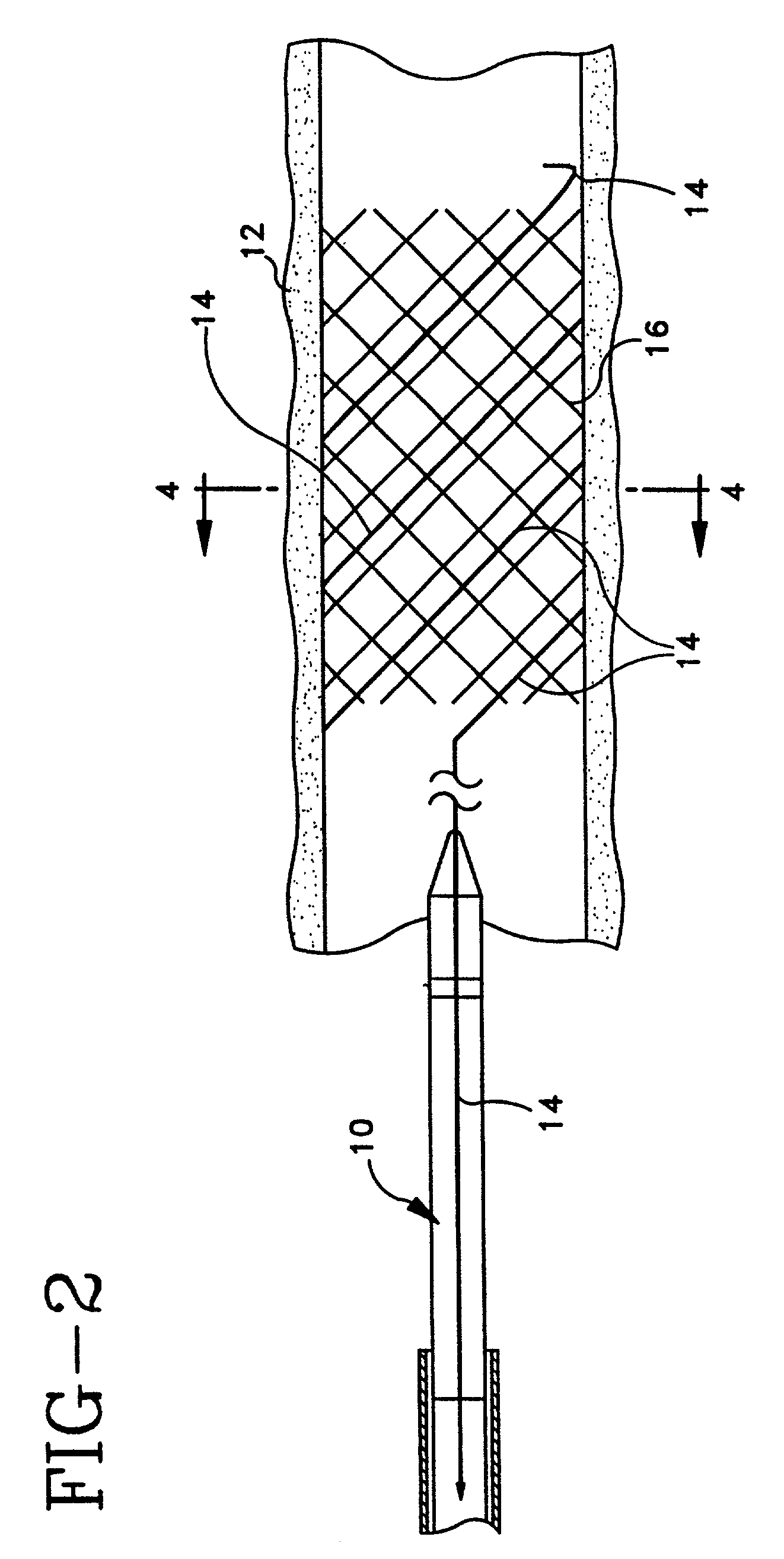
[0057]A retrievable, temporary radiopaque marker can be in the form of a strand of metal or polymer containing radiopaque elements, oxides, or salts of elements with atomic numbers in the range of from about 22 to about 83 loosely threaded along a helical, circumferential, or axial orientation in an endoprosthesis such as a stent, stent-graft, graft, filter, occlusive device, and valve with a free end of the marker extending out from the endoprosthesis such that it is attached to the delivery system or passed outside of the body and the marker and is separated from the implanted endoprosthesis by pulling it free and out of the body. The radiopaque material has a linear attenuation coefficient of from about 5.46 cm−1 at 50 KeV to about 151.53 cm−1 at 50 KeV.

example 2

[0058]A retrievable, temporary radiopaque marker can be in the form of a strand of metal or polymer containing radiopaque elements, oxides, or salts of elements with atomic numbers in the range of from about 22 to about 83 formed into a spring and disposed within an endoprosthesis such as a stent, stent-graft, graft, filter, occlusive device, and valve with a free end of the marker extending out from the endoprosthesis such that it is attached to the delivery system or passed outside of the body and the marker and is separated from the implanted endoprosthesis by pulling it free and out of the body. The radiopaque material has a linear attenuation coefficient of from about 5.46 cm−1 at 50 KeV to about 151.53 cm−1 at 50 KeV.

example 3

[0059]A retrievable, temporary radiopaque marker can be in the form of a strand of ductile metal wire, ribbon, or braided wire containing radiopaque metallic elements with atomic numbers in the range of from about 22 to about 83, preferably titanium, tantalum, zirconium, and platinum disposed within an endoprosthesis such as a stent, stent-graft, graft, filter, occlusive device, and valve with a free end of the marker extending out from the endoprosthesis such that it is attached to the delivery system or passed outside of the body and the marker and is separated from the implanted endoprosthesis by pulling it free and out of the body. The radiopaque material has a linear attenuation coefficient of from about 5.46 cm−1 at 50 KeV to about 149.08 cm−1 at 50 KeV.


PUM


Abstract

A temporary and retrievable radiopaque marker and discrete radiopaque marker for use on an implantable endoprosthesis. The elongate marker has a proximal end, a distal end, and a thickness. At least a portion of the marker is radiopaque and the marker is removably-attached to the implantable endoprosthesis.

Description

[0001]This is a divisional of prior application Ser. No. 08 / 905,821, filed Aug. 1, 1997, now U.S. Pat. No. 6,340,367.BACKGROUND OF THE INVENTION[0002]This invention relates generally to a retrievable radiopaque marker or a discrete radiopaque marker for use on an implantable endoprosthesis such as a stent.[0003]Implantable endoprostheses including stents, stent-grafts, and grafts are used in percutaneous transluminal coronary angioplasty and in other medical procedures to repair and support diseased or damaged arteries and body lumens. Grafts are implanted to cover or bridge leaks or dissections in vessels. Stent-grafts are stents which generally have a porous coating attachment and may be implanted by percutaneous transluminal angioplasty. Unsupported grafts are porous tubes which are typically implanted by surgical cut-down.[0004]In order to visualize the passage and placement of the implantable endoprosthesis in arteries and body lumens, many surgical procedures are performed und...

Claims


Application Information

Patent Timeline
IPC IPC(8): A61F2/06A61F2/00A61F2/82A61F2/86A61F2/90
CPCA61F2/82A61F2/90A61F2/86A61F2220/005A61F2250/0059A61F2250/0098
Inventor STINSON, JONATHAN S.CLERC, CLAUDE O.
Owner SCHNEIDER (USA) INC
Learn More