Contactless charging method for charging battery

a charging method and battery technology, applied in circuit monitoring/indication, transportation and packaging, transmission, etc., can solve the problems of unreliable power supply, easy loss of charged energy, and inability to disclose power supply, so as to prevent unnecessary power consumption

Active Publication Date: 2012-03-06
LS CABLE & SYST LTD
View PDF26 Cites 93 Cited by
  • Summary
  • Abstract
  • Description
  • Claims
  • Application Information

AI Technical Summary

Benefits of technology

[0011]In addition, still another object of the present invention is to supply a charging power after the primary coil and the secondary coil are magnetically completely coupled so as to prevent an unnecessary power consumption.

Problems solved by technology

However, if a contact terminal is exposed out as mentioned above, an appearance is deteriorated and the contact terminal is contaminated due to external impurities to easily cause an inferior contact status.
In addition, if the battery is short-circuited or exposed to moisture due to the carelessness of a user, the charged energy may be easily lost.
However, Korean Laid-open Publication No. 2004-87037 does not disclose a power supplier for feeding back charging status information (e.g., charging current, charging voltage, etc.) and generating a charging power corresponding to the charging status information, or a contactless charger system using such a power supplier.

Method used


Image

  • Contactless charging method for charging battery
  • Contactless charging method for charging battery
  • Contactless charging method for charging battery

Examples


Embodiment Construction

[0038]Hereinafter, preferred embodiments of the present invention will be described in detail with reference to the accompanying drawings. Prior to the description, it should be understood that the terms used in the specification and the appended claims should not be construed as limited to general and dictionary meanings, but interpreted based on the meanings and concepts corresponding to technical aspects of the present invention on the basis of the principle that the inventor is allowed to define terms appropriately for the best explanation. Therefore, the description proposed herein is just a preferable example for the purpose of illustrations only, not intended to limit the scope of the invention, so it should be understood that other equivalents and modifications could be made thereto without departing from the spirit and scope of the invention.

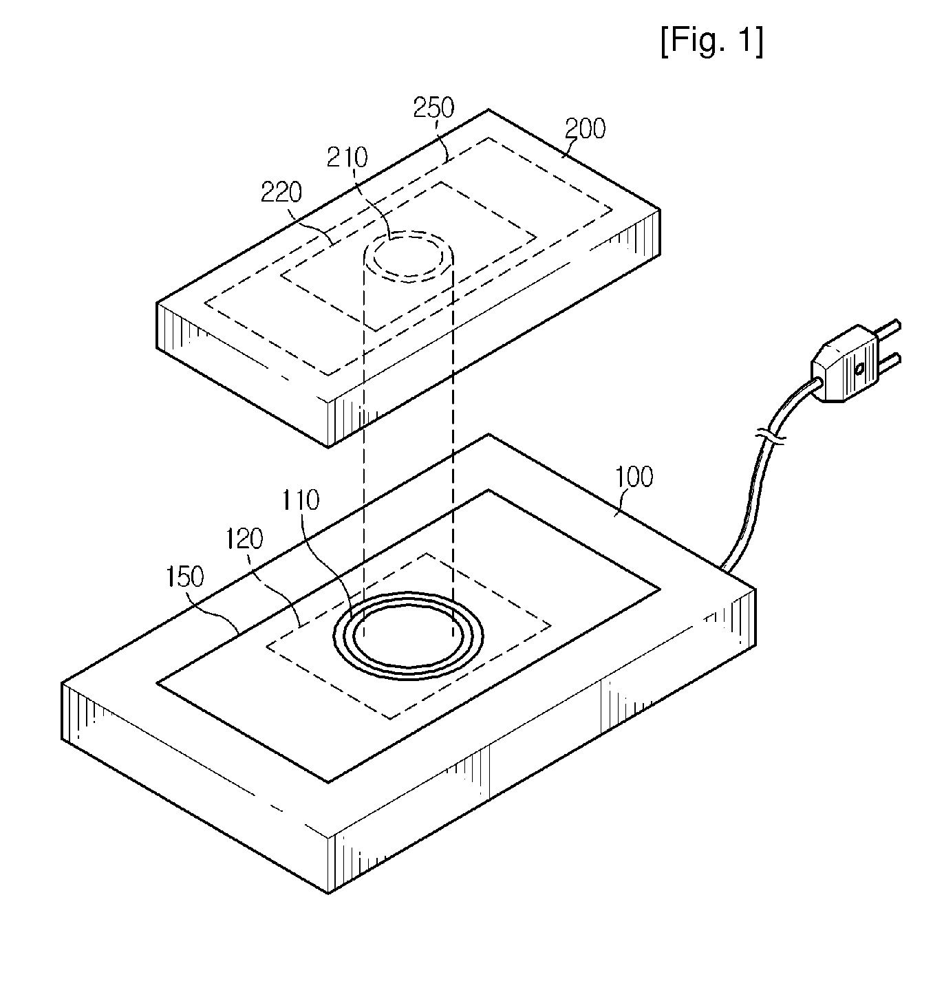
[0039]FIG. 1 is a schematic perspective view showing a contactless charger system according to a preferred embodiment of the present i...


PUM


Abstract

A system, method and apparatus for contact-less charging of battery operated devices is presented. There is a host charger with a power converter and resonant tank circuit and a portable device where the battery is located, with a battery charging control IC. The method obviates the need for a voltage controller in each of both the host and the portable stages, thus decreasing complexity and increasing efficiency. The charging of the battery in the portable device is controlled by a charging controller therein, which is in continual electric communication with the host, whose output power the control IC dynamically monitors and controls. Two embodiments for the charging circuitry in the portable device are presented. In one embodiment component count is minimized but battery charging is not optimized when the battery voltage is very low. In the other embodiment charging efficiency is maximized regardless of the output voltage of the battery, but additional components are utilized.

Description

CROSS-REFERENCE TO RELATED APPLICATIONS[0001]This application is a national stage application under 35 U.S.C. 371 based on and claiming the benefit of International Application Serial No. PCT / KR2006 / 002695 filed on Jul. 10, 2006 and the benefit of priority from Korean Application No. 10-2005-69962 filed on Jul. 30, 2005 the entire contents of each of which are incorporated herein by reference.TECHNICAL FIELD[0002]The present invention relates to a charging device of a portable electronic device, and more particularly to a contactless charger system using inductive coupling.BACKGROUND ART[0003]A rechargeable secondary battery is mounted to a portable electronic device such as a mobile communication terminal and PDA. To charge the secondary battery, a separate charging device for supplying an electric energy to the battery of a portable electronic device using an AC line power is required. Generally, separate contact terminals are respectively provided to outsides of the charging devi...

Claims


Application Information

Patent Timeline
Patent Type & Authority Patents(United States)
IPC IPC(8): H02J7/14H02J7/00
CPCH02J7/025H02J7/0044H02J50/80H02J50/10H02J7/0047H04B5/0075H04B5/0037H02J2310/22
Inventor PARK, DONG-YOUNGMOON, SUNG-WOOKCHOI, SUNG-WOOKGWON, GWANG-HEEHAN, SUBKIM, JUNG-BUM
Owner LS CABLE & SYST LTD
Why Eureka
Try Eureka