System and method for target signature calculation and recognition

a target object and signature technology, applied in the direction of measurement devices, radio wave direction/deviation determination systems, instruments, etc., can solve the problems of increasing the cost of construction and operation of radar systems, increasing the cost of target object identification determination, and increasing the cost of tracking systems. , to achieve the effect of improving the detection ability of targets, high signal energy, and low cost of a pcl system

Active Publication Date: 2012-03-06
LOCKHEED MARTIN CORP
View PDF10 Cites 2 Cited by
  • Summary
  • Abstract
  • Description
  • Claims
  • Application Information

AI Technical Summary

Benefits of technology

[0018]In addition to its covertness aspects, use of PCL can provide enhanced detectability of targets because of the extremely high energy of the signals used by the concept. In some cases, inherent sensitivities of up to 2 orders of magnitude greater than radar are possible. Furthermore, there is no scanning mechanism necessary in PCL. For this reason, target updates are not slaved to the mechanical rotation of antennas or intermittent pulses, and all targets may be updated as rapidly as desired. Real-time systems have been built with update rates of 6 per second for all targets within the system purview. Cost of a PCL system tends to be low when compared with that of a radar system, and reliability is high because of the lack of need for any scanning or high-energy RF power transmission.
[0019]The inherent ability of PCL to provide simultaneous high-quality tracking of multiple objects within a large volume of space is a departure from the method which radar uses for object tracking. With radar, the typical radar system revisits a multiplicity of objects sequentially by a scanning beam in order to maintain track on the objects. In PCL, the receiver beams are created and processed simultaneously in order to provide wide angular coverage.
[0021]Under typical PCL use, many transmitters are exploited simultaneously. Using multiple transmitters increases the accuracy of the signature data due to the ability to compare and correlate the measurements across the transmitters. Comparing the data to a best mathematical representation of an expected signal return for a calculated wavelength may also be used to filter the signal returns of the target object for increased accuracy.
[0022]To identify a target object, the PCL system compares one or more features of a target object with a database of known aircraft features. The target object features used in the comparison may be one or more of the calculated dimensions of the target object, the velocity of the target object, the altitude of the target object, or any other feature discernable by the PCL system. The known aircraft features database provides a loosely populated decision space for the features calculated with the PCL system allowing for an accurate identification of a target object. For these reasons, PCL is well suited for detecting and identifying target objects.

Problems solved by technology

The inability to continually track a target object raises the chance that a tracking system will generate inconsistent information among each sampling of data.
The inclusion of scanning mechanisms and high-energy RF power transmission also tend to increase the cost of construction and operation of a radar system.
These calculations will typically be done at intervals that allow for substantial movement of the target object between each calculation, adding significant complexity to the determination of the identity of the target object.
These and other deficiencies exist in current object recognition systems.

Method used


Image

  • System and method for target signature calculation and recognition
  • System and method for target signature calculation and recognition
  • System and method for target signature calculation and recognition

Examples


Embodiment Construction

[0039]Reference will now be made in detail to various embodiments of the present invention, examples of which are illustrated in the accompanying drawings.

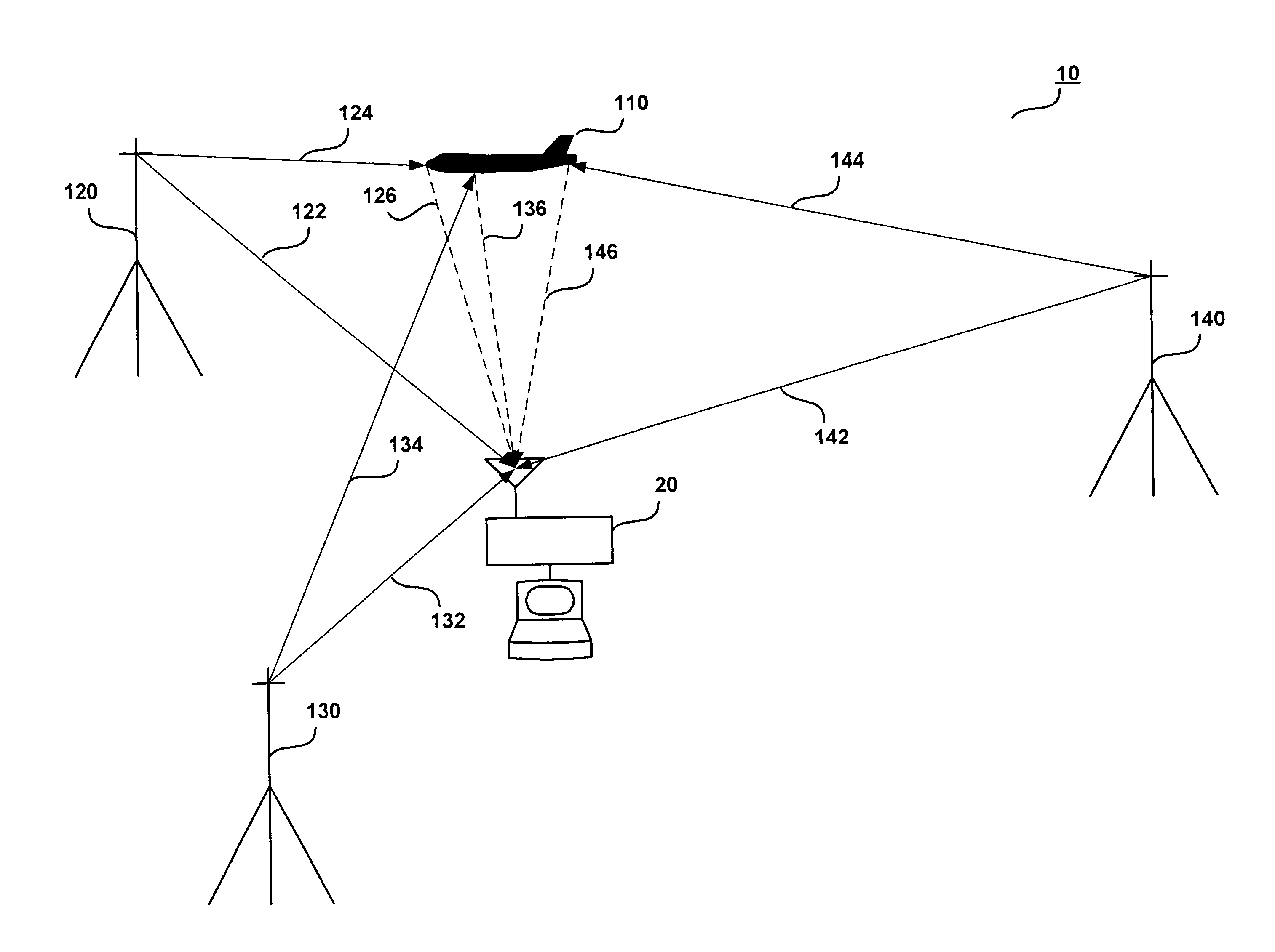
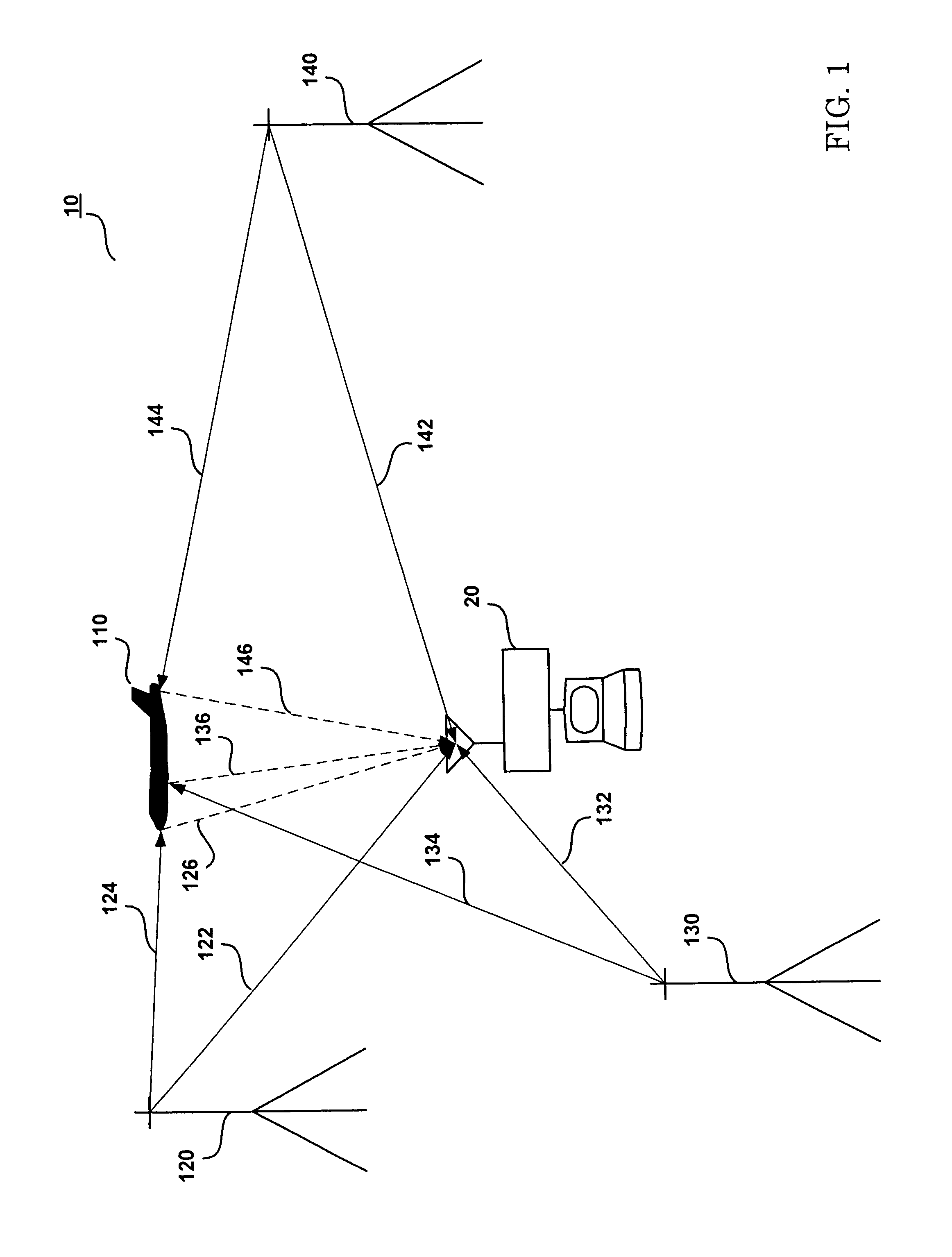
[0040]FIG. 1 illustrates a conventional PCL target-tracking configuration 10. This configuration 10 includes a PCL signal processing unit 20, a target object 110, and a plurality of transmitters 120, 130, and 140. Accordingly, the PCL signal processing unit 20 receives direct RF signals 122, 132, and 142 broadcast by transmitters 120, 130, and 140, as well as reflected RF signals 126, 136, and 146. The reflected RF signals 126, 136, and 146 are also broadcast by transmitters 120, 130, and 140 and are reflected by the target object 110.

[0041]In a typical target-tracking configuration, the PCL processing unit 20 calculates the time-difference-of-arrival (TDOA), frequency-difference-of-arrival (FDOA) (also known as the Doppler shift), and / or other information from the direct RF signals 122, 132, and 142 and the reflected RF signals 1...


PUM


Abstract

The present invention is directed to a system and method for the identification of a target object in PCL radar applications. The disclosed embodiments describe the systems and methods used in the identification of a target object from the collection of data representing specific target object features, such as velocity, altitude, fuselage length, wing length, or wing sweepback angle, and the comparison of selected target object features with a database of known aircraft features. The present invention also provides for the calculation of feature dimensions, such as the fuselage length, wing length, or wing sweepback angle from measurements associated with a peak signal lobe as a function of a bistatic aspect angle.

Description

CROSS REFERENCE TO RELATED APPLICATIONS[0001]This application claims benefit of U.S. Provisional Application No. 60 / 364,030 entitled “SYSTEM AND METHOD FOR TARGET SIGNATURE CALCULATION AND RECOGNITION” and filed Mar. 15, 2002, which is hereby incorporated by reference.BACKGROUND OF THE INVENTION[0002]1. Field of the Invention[0003]The present invention relates to the detection, tracking and recognition of a target object, and more particularly, to a system and method for calculating a signature for recognition of a target object.[0004]2. Discussion of the Related Art[0005]The detection and tracking of a target object is typically accomplished with radio detection and ranging, commonly known as radar. Radar systems typically emit electromagnetic energy and detect the reflection of that energy scattered by a target object. By analyzing the time difference of arrival, Doppler shift, and various other changes in the reflected energy, the location and movement of the target object can be...

Claims


Application Information

Patent Timeline
Patent Type & Authority Patents(United States)
IPC IPC(8): G01S13/00G01S13/46G01S7/02G01S7/41
CPCG01S7/411G01S13/003G01S3/16
Inventor LODWIG, RICHARD A.LODWIG, LEGAL REPRESENTATIVE, SANDRALODWIG, LEGAL REPRESENTATIVE, RICHARDADAMS, BONNIE L.
Owner LOCKHEED MARTIN CORP
Why Eureka
Try Eureka