
Method, medium and apparatus detecting model collisions

a collision detection and model technology, applied in the field of collision detection, can solve the problems of long examination time, complicated model shapes, and failure of collision detection apparatus, and achieve the effect of quick examination

Active Publication Date: 2012-03-06
SAMSUNG ELECTRONICS CO LTD
View PDF22 Cites 3 Cited by
  • Summary
  • Abstract
  • Description
  • Claims
  • Application Information

AI Technical Summary

Benefits of technology

The present invention provides a method and apparatus for detecting collisions between models that are enveloped by model primitives. The method and apparatus can quickly examine whether models collide with each other and recognize the collision at an arbitrary time, regardless of whether the collision occurs at a predetermined check time. This allows for faster and more efficient detection of collisions between models, improving efficiency and accuracy.

Problems solved by technology

A conventional model collision detection apparatus determines whether such a collision occurs at one or more predetermined collision check times. Accordingly, the conventional model collision detection apparatus cannot recognize a collision if the collision occurs at a time which does not fall within the predetermined collision check times. As a result, a problem exists in that the conventional model collision detection apparatus may fail to recognize the collision when the collision occurs at a time that is not a predetermined collision check time.
Also, since the conventional model collision detection apparatus determines whether models collide with each other by detecting whether parts of the models overlap, the examination takes a long time to perform as the shapes of the models are complicated.
As a result, the conventional model collision detection apparatus cannot quickly examine whether models collide with each other, particularly when the complexity of the shape of a model is high.

Method used


Image

  • Method, medium and apparatus detecting model collisions
  • Method, medium and apparatus detecting model collisions
  • Method, medium and apparatus detecting model collisions

Examples


Embodiment Construction

[0023]Reference will now be made in detail to embodiments, examples of which are illustrated in the accompanying drawings, wherein like reference numerals refer to the like elements throughout. Embodiments are described below to explain the present invention by referring to the figures.

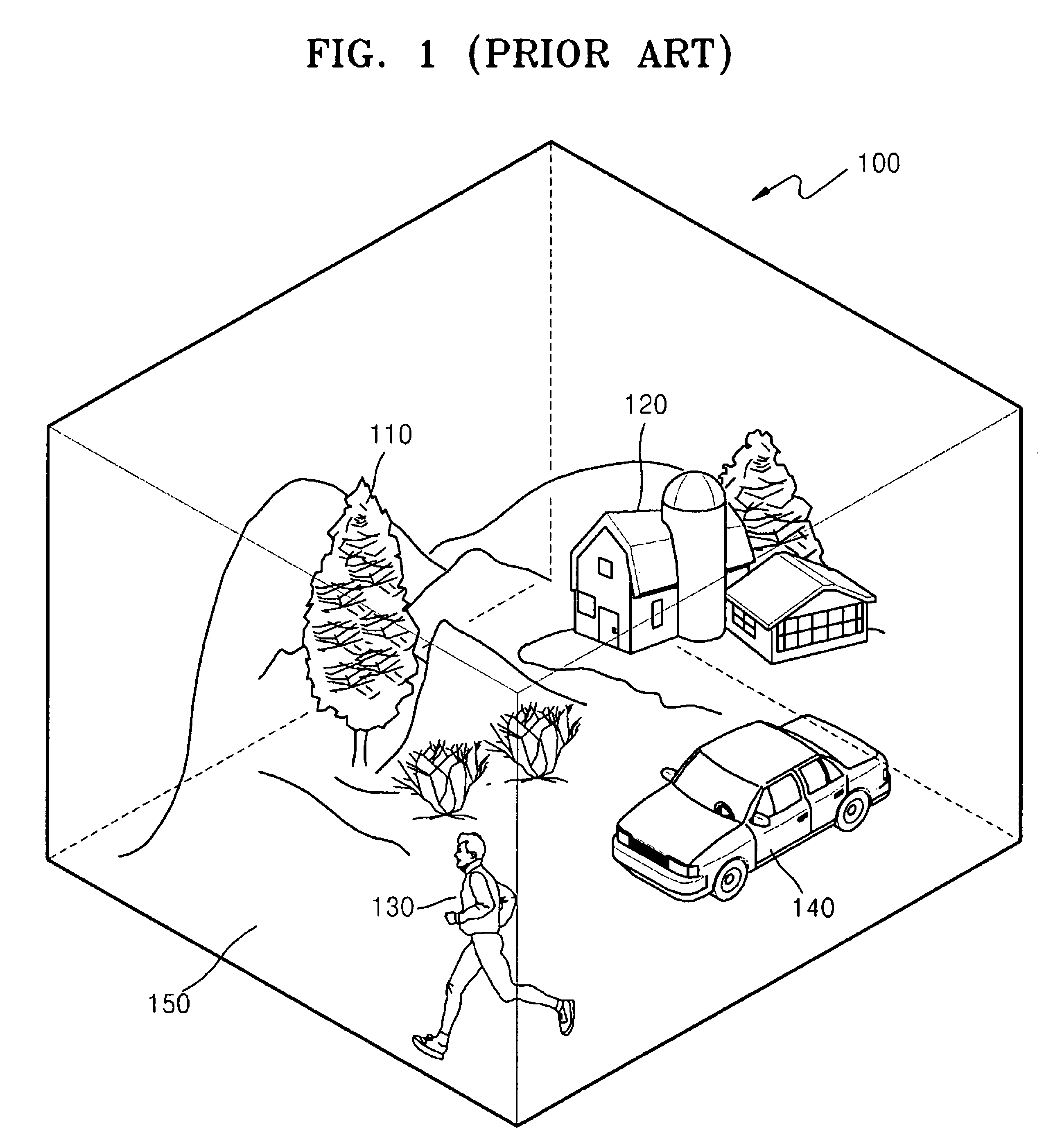
[0024]FIG. 1 explains a scene 100, including objects 110, 120, 130, and 140, and a background 150.

[0025]The scene 100 refers to a three-dimensional space in which information that is to be rendered may be contained. The scene 100 may include one or more objects, such as objects 110, 120, 130, and 140, and background 150, for example. Here, objects 110, 120, 130, or 140 may be static objects such as a tree 110 or a house 120, or may be dynamic objects such as a moving person 130 or a moving car 140. Meanwhile, the background 150 typically refers to a setting (for example, the sky or ground) at which the objects 110, 120, 130, or 140 may be positioned. In an embodiment, the locations of the dynamic obje...


PUM


Abstract

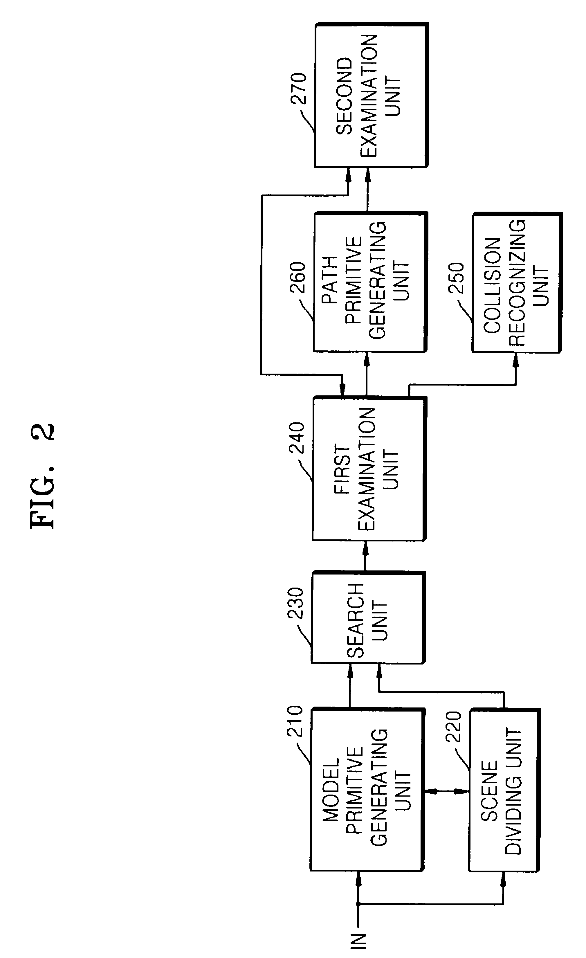
A method, medium and apparatus determining whether models collide with each other. In the model collision detecting method, medium and apparatus, it is possible to quickly examine whether models collide, and to recognize the collision generated at an arbitrary time, which is not a predetermined collision check time of the models, without missing the recognition of the collision generated at the arbitrary time, by determining whether paths reflecting movement of the model primitives between the current time and a previous time overlap when the model primitives do not collide at the current time, determining whether the model primitives collide with each other at an arbitrary time between the current time and the previous time when the path primitives overlap each other, and recognizing that the models collide with each other at the arbitrary time when the model primitives collide with each other at the arbitrary time.

Description

CROSS-REFERENCE TO RELATED APPLICATIONS[0001]This application claims the benefit of Korean Patent Application No. 10-2007-0011270, filed on Feb. 2, 2007, in the Korean Intellectual Property Office, the disclosure of which is incorporated herein in its entirety by reference.BACKGROUND[0002]1. Field[0003]One or more embodiments of the present invention relate to collision detection, and more particularly, to a method, medium and apparatus detecting collisions between models included in a scene.[0004]2. Description of the Related Art[0005]In computer modeling, a conventional model collision detection apparatus determines whether models collide with each other, and recognizes a collision between the models if it is determined that the models do collide with each other. Such a model collision detection apparatus has to quickly detect collisions between models without missing any collisions, regardless of when the collisions might occur. For example, in the case of a three-dimensional (3D...

Claims


Application Information

Patent Timeline
Patent Type & Authority Patents(United States)
IPC IPC(8): G06T17/10
CPCG06T17/00G06T2210/21G06F17/00
Inventor AHN, JEONG-HWANLEE, KEE-CHANG
Owner SAMSUNG ELECTRONICS CO LTD
Learn More