
Medical device for fluid flow and method of forming such device

a technology of fluid flow and medical device, applied in the field of medical device, can solve problems such as being unable to act against pressure increas

Active Publication Date: 2012-03-13
BARD PERIPHERAL VASCULAR
View PDF49 Cites 8 Cited by
  • Summary
  • Abstract
  • Description
  • Claims
  • Application Information

AI Technical Summary

Benefits of technology

The present invention relates to medical devices such as implants and tubing that come into contact with bodily fluid when used in dialysis or open heart surgery. The invention aims to improve the thrombogenic effect caused by the contact between blood and artificial surfaces. The invention proposes the use of a medical device with a wall surface that has a series of protuberances placed on it. These protuberances create a modified flow pattern that reduces the effects of fluid stagnation and turbulence. The patent text also describes the optimal spacing, height, and shape of the protuberances to achieve the desired flow pattern. Overall, the invention provides a medical device that reduces the risk of thrombogenic events and improves the flow of bodily fluid through it.

Problems solved by technology

This increased pressure forces fluid layers close to the luminal wall, which have already been slowed down to a large extent by friction and thus not being able to act against the pressure increase, to a reverse flow.

Method used


Image

  • Medical device for fluid flow and method of forming such device
  • Medical device for fluid flow and method of forming such device
  • Medical device for fluid flow and method of forming such device

Examples


Embodiment Construction

[0049]The drawings attached hereto are schematic and not to scale.

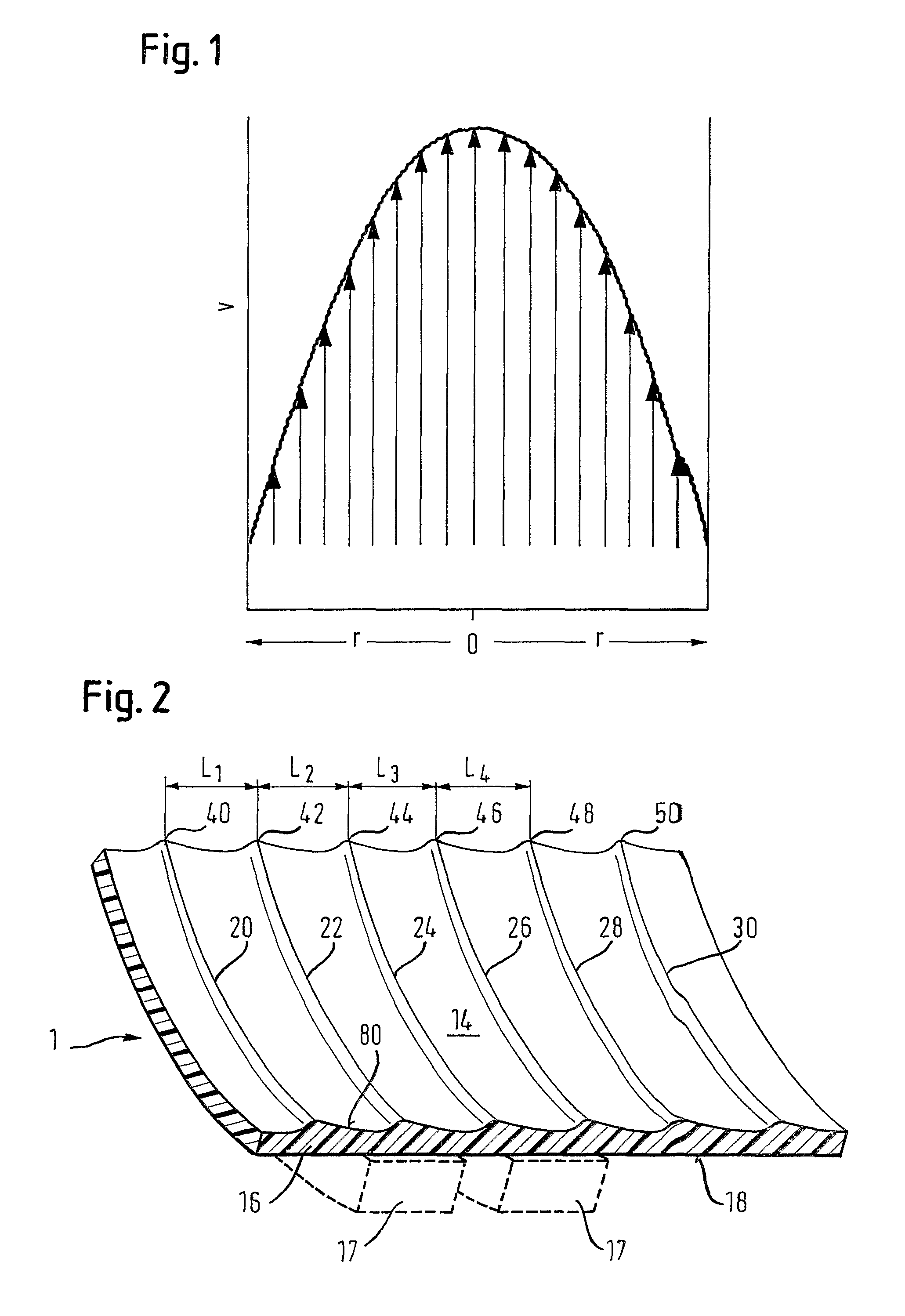
[0050]FIG. 1 has been explained already above.

[0051]FIG. 2 shows an isometric view of a portion of the length of an e-PTFE cylindrical graft or tube 1. The present invention, however, is not limited to specific materials. Rather, any suitable material like e-PTFE or DACRON® can be used, depending only on the medical compatibility. For the sake of clarity, the drawing of FIG. 2 shows only a part of the circumference of the tube 1.

[0052]From FIG. 2 it can be seen that the luminal wall 14 of the tube, which marks the inside surface 80 of the wall thickness 16 of the tube, is itself not cylindrical, unlike the abluminal surface 18 of the tube, which is cylindrical. It is, however, contemplated that also the abluminal surface 18 of the tube does not necessarily have to be cylindrical. In addition, the overall form of the tube does not have to cylindrical, the tube can also have one or more branches, which themselves might ...


PUM

PropertyMeasurementUnit
heightaaaaaaaaaa
heightaaaaaaaaaa
distanceaaaaaaaaaa

Abstract

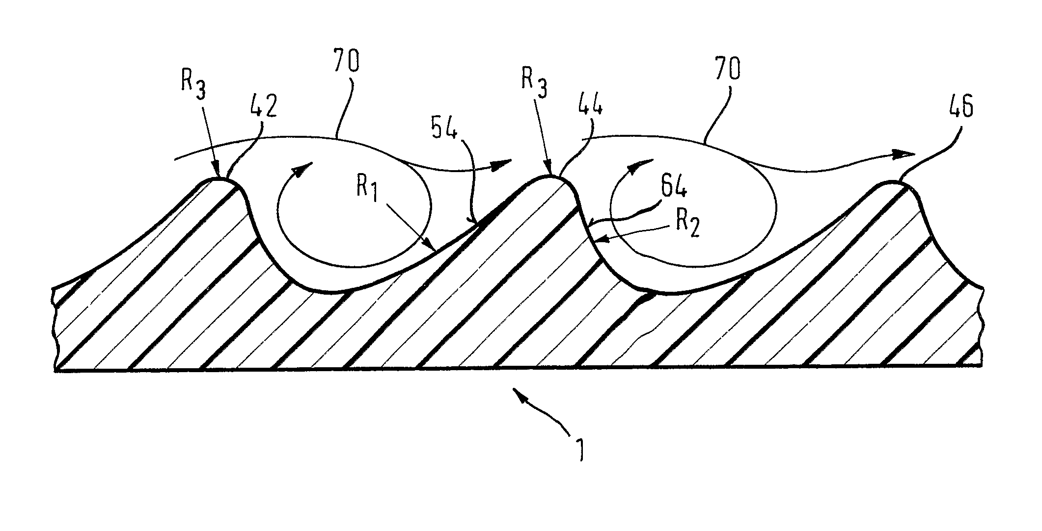
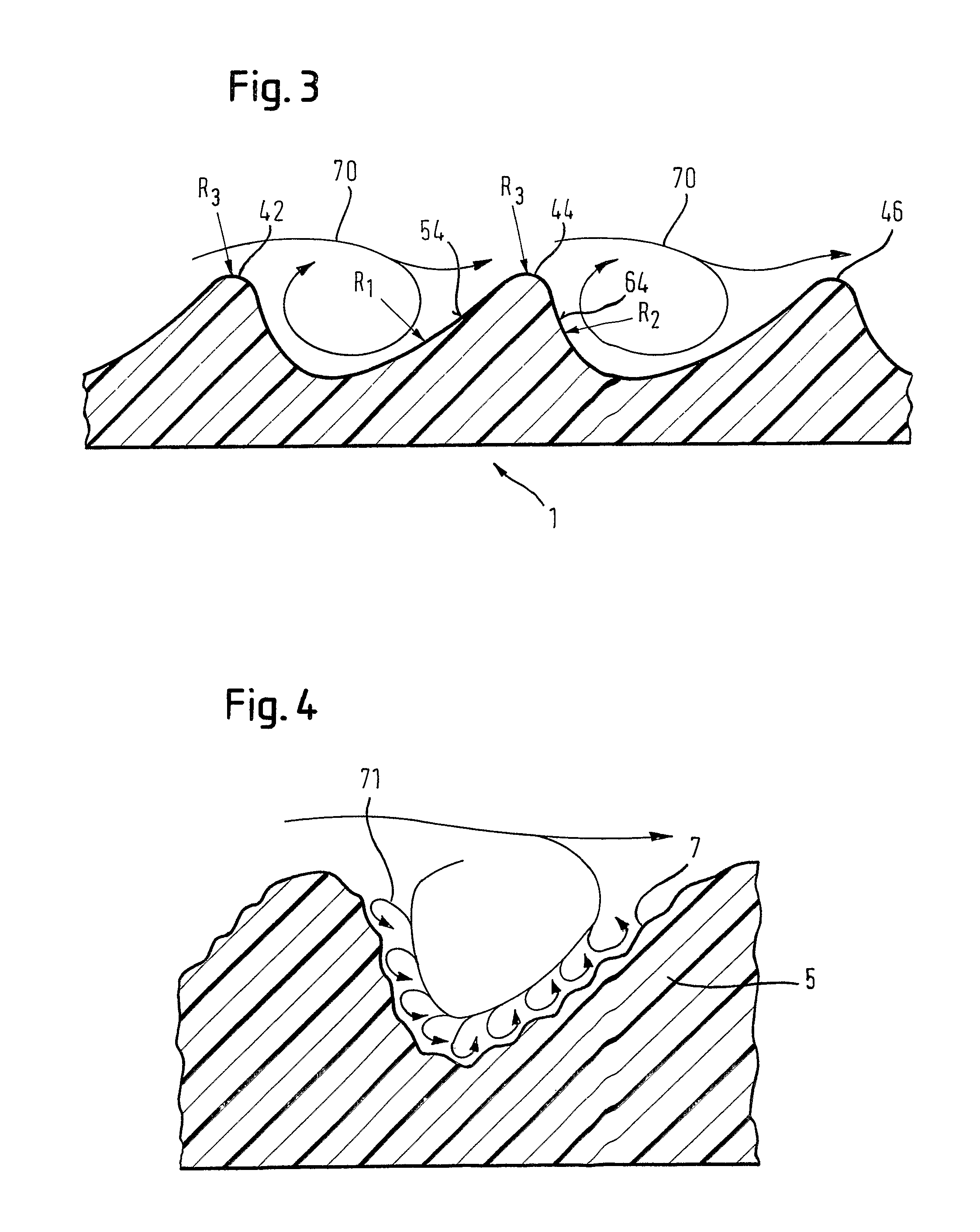
A medical device which defines a lumen for flowing a bodily fluid from an upstream end of the device to a downstream end thereof is disclosed. The device has a luminal wall (14) that extends between the upstream and downstream ends and defines the lumen within which the fluid flows. The wall exhibits a succession of protuberances spaced from each other along the length of the device. Each protuberance has a flank facing upstream (54) and a flank facing downstream (64), the flank facing upstream extending into the fluid flow so that a radially outermost part of the flow of fluid from the upstream to the downstream end of the device impinges on the upstream flank and is thereby caused to reverse its flow, and flow upstream from the upstream flank to the downstream flank of the next adjacent protuberance upstream, creating micro-vortices between two adjacent protuberances.

Description

PRIORITY[0001]This application is a national stage application under 35 USC 371 of International Patent Application No. PCT / EP2005 / 011351, filed Oct. 21, 2005, claiming priority to United Kingdom Patent Application No. GB 0423422.5, filed Oct. 21, 2004, each of which is incorporated by reference into this application as if fully set forth herein.FIELD OF THE INVENTION[0002]The present invention relates to medical devices which define a lumen for flowing a bodily fluid from an upstream end of the device to a downstream end thereof. More particularly, the present invention relates to medical devices which define a lumen for flowing blood and which have a wall surface that inhibits adhesion of material out of the bodily fluid onto the wall surface of the lumen.BACKGROUND OF THE INVENTION[0003]Disturbance of arterial blood circulation is one of the most common diseases in industrial countries. Mostly, the cause of this disease is arteriosclerosis, which leads to a constriction or even o...

Claims


Application Information

Patent Timeline
Patent Type & Authority Patents(United States)
IPC IPC(8): A61F2/02A61F2/04A61M1/10A61F2/24A61F2/06B29C48/32
CPCA61F2/06Y10T156/1007A61F2002/068
Inventor SCHOLZ, HANSPETZOLD, KARENKRUGER, ULF
Owner BARD PERIPHERAL VASCULAR
Learn More