System and method for multi-channel recording

a multi-channel recording and recording system technology, applied in the field of call recording systems and methods, can solve the problems of difficult to distinguish which side of the call the background audio, difficult to decipher what either party said, and difficult to distinguish between human or robotic reviewers, so as to achieve accurate re-creation and greater flexibility

Inactive Publication Date: 2012-03-13
SECURUS TECH
View PDF13 Cites 345 Cited by
  • Summary
  • Abstract
  • Description
  • Claims
  • Application Information

AI Technical Summary

Benefits of technology

[0008]Further, in many instances, it is desirable to re-create a call from the perspective of any selected party. For instance, it may be desirable to selectively hear a recorded call from the perspective of an originating party, or from the perspective of the called party, etc. With the traditional single-channel recording techniques, the recording is limited to capturing only a single perspective at a time. Thus, for a given portion of a call, a reviewer of a call is limited to a recording of only a single perspective in the traditional single-channel recording techniques, and the reviewer is unable to selectively listen to such portion of the call from a different perspective than that captured by the recording system. Accordingly, a desire exists for a recording system that enables greater flexibility in accurately re-creating calls from many different perspectives.
[0009]Embodiments of the present invention

Problems solved by technology

In some instances, such a single-channel recording technique results in difficulty in a reviewer (either human or robotic reviewer) distinguishing what each party to a call said.
For example, suppose a recording is being captured from an eavesdropper's perspective; in this case, where conversations overlap (e.g., two or more parties are speaking at the same time), it may be difficult to decipher what either party said.
Further, it may be difficult to distinguish which side of a c

Method used


Image

  • System and method for multi-channel recording
  • System and method for multi-channel recording
  • System and method for multi-channel recording

Examples


Embodiment Construction

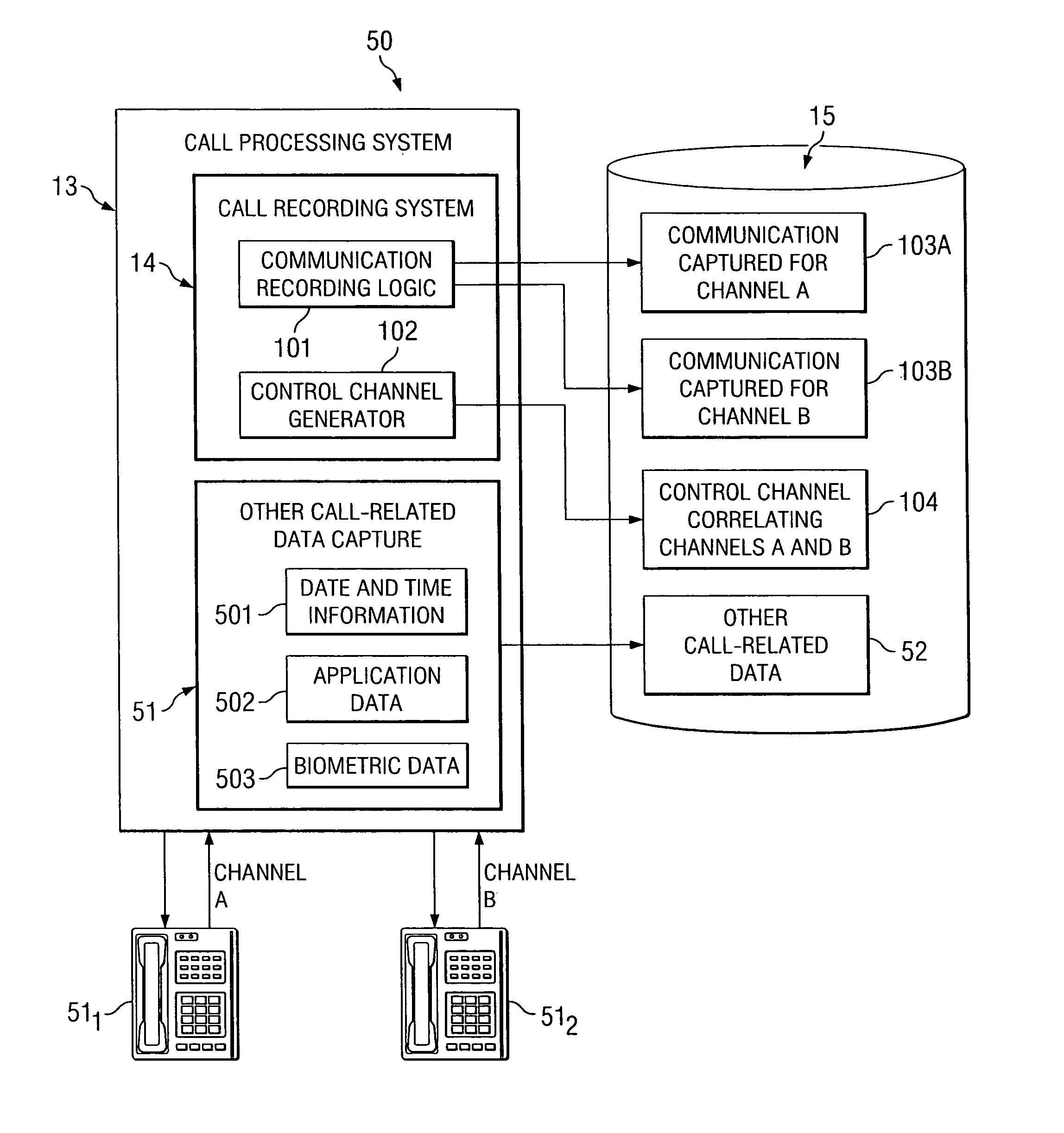
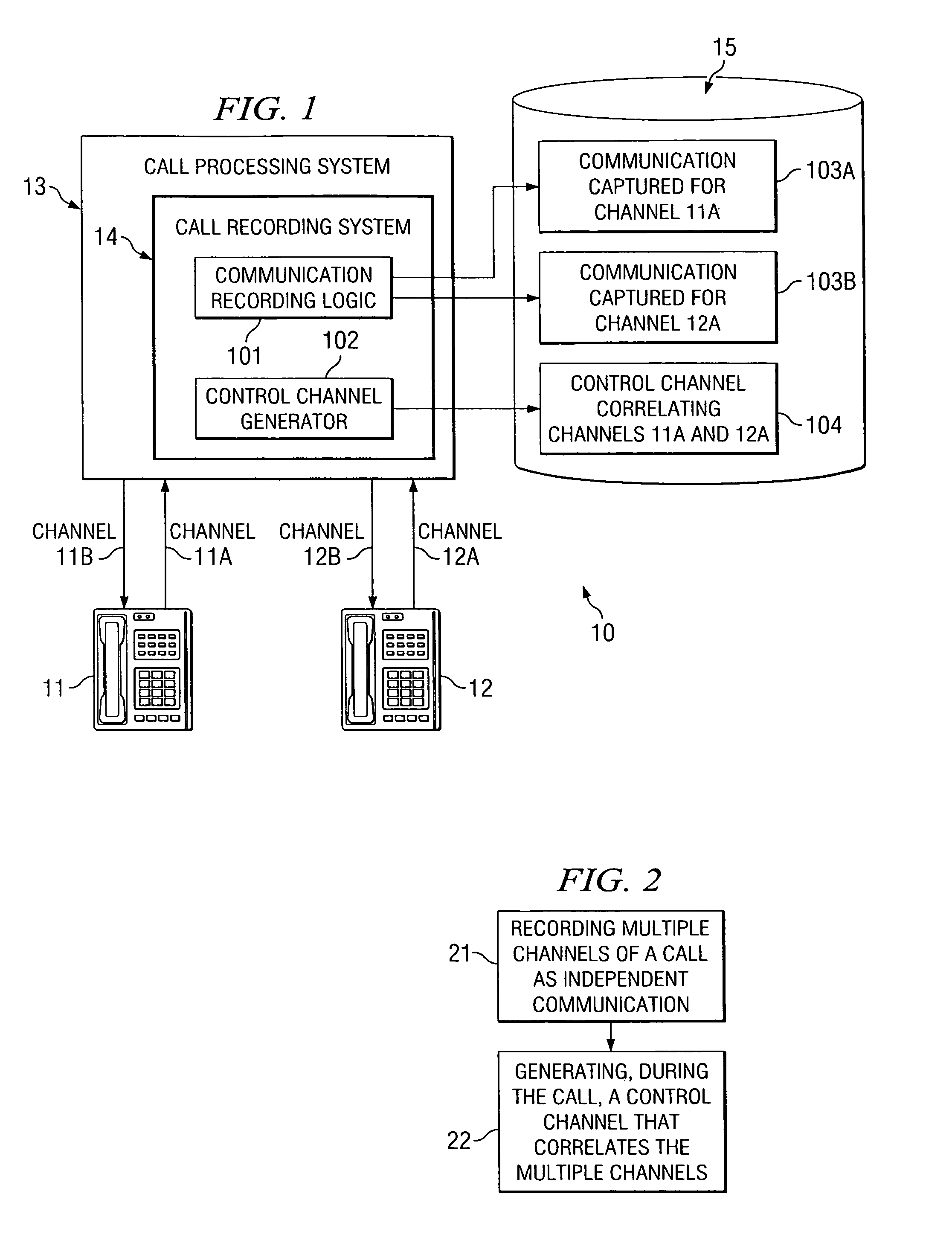
[0020]FIG. 1 shows an exemplary system 10 according to one embodiment of the present invention. System 10 comprises a first communication device 11 and a second communication device 12, which are operable to communicate with each other. While two communication devices are shown for simplicity in this example, any number of communication devices may participate in a call according to embodiments of the present invention. In this example, first and second communication devices 11 and 12 are shown as telephones; although as discussed further herein, embodiments of the present invention are not limited in application to telephony communication devices. System 10 also comprises a call processing system 13, which is operable to process a call. Call processing system 13 may perform various types of processing on a call, including billing the call, performing checks to ensure that the call is authorized (e.g., in the context of a correctional facility, an inmate may not be authorized to pla...


PUM


Abstract

Embodiments of the present invention are directed generally to recording communication of a call utilizing a multi-channel recording technique. According to one exemplary embodiment, inbound communication from each party to a call (e.g., from each communication device that is party to a call) to a recording system is assigned to a separate channel, and communication on each channel is independently recorded. Further, during the call, a control channel is generated that correlates the multiple communication channels. The independently recorded communication channels and control channel may be used to analyze a recorded call from any desired perspective. For instance, communication from a given party may be analyzed in isolation. Further, the control channel enables the recorded multiple communication channels to be correlated such that the communication received (e.g., heard) by any selected party may be accurately re-created for analysis thereof.

Description

CROSS-REFERENCE TO RELATED APPLICATIONS[0001]This application is related to co-pending and commonly assigned U.S. patent application Ser. No. 10 / 135,878, filed Apr. 29, 2002, titled “INFORMATION MANAGEMENT AND MOVEMENT SYSTEM AND METHOD”; Ser. No. 10 / 720,848, filed Nov. 24, 2003, titled “INFORMATION MANAGEMENT AND MOVEMENT SYSTEM AND METHOD”; Ser. No. 10 / 420,585 filed Apr. 22, 2003, titled: “SYSTEM AND METHOD FOR DETECTING UNAUTHORIZED CALL ACTIVITY”; Ser. No. 11 / 334,522 filed Jan. 18, 2006, titled “SYSTEM AND METHOD FOR KEYWORD DETECTION IN A CONTROLLED ENVIRONMENT FACILITY USING A HYBRID APPLICATION”; and U.S. Pat. No. 7,058,163, titled “SYSTEM AND METHOD FOR EX POST FACTO PRESERVING A RECORDED CONVERSATION”, the disclosures of which are hereby incorporated herein by reference.TECHNICAL FIELD[0002]The following description relates generally to call recording systems and methods, and more particularly to systems and methods for recording a call via multiple channels.BACKGROUND OF T...

Claims


Application Information

Patent Timeline
IPC IPC(8): H04M1/64
CPCH04M1/64
Inventor HOGG, JR., JOHN S.MCFARLEN, CHRISTOPHER R.
Owner SECURUS TECH
Why Eureka
Try Eureka