Method and device for monitoring the dynamic behavior of a rotating shaft, in particular of a gas or steam turbine

a rotating shaft and dynamic behavior technology, applied in the direction of gas-turbine engine testing, material analysis using wave/particle radiation, instruments, etc., can solve the problems of damage to the machine, high cost and downtime periods, and avoid early switching off or powering down the machine, and avoid the effect of downtim

Active Publication Date: 2012-03-20
SIEMENS ENERGY GLOBAL GMBH & CO KG
View PDF13 Cites 2 Cited by
  • Summary
  • Abstract
  • Description
  • Claims
  • Application Information

AI Technical Summary

Benefits of technology

[0007]The knowledge underlying the invention is as follows: If the vibration of the shaft exceeds a specific value, this can lead to the machine being switched off or is typically associated with the machine being powered down. This however involves high costs and periods of downtime. If the machine is not switched off in good time, the vibrations cause serious damage to the machine. The vibrations can be measured by sensors. The invention is also based on the knowledge that the different frequency ranges in respective different directions, starting from the center point of the shaft, can cause damage to the machine. The reason for this is that in different frequency ranges the amplitude in the different directions is strongly developed. The frequency range for damage to the machine is thus different in the different directions. This means that vibrations in a specific frequency range thus damage the machine especially in a particular direction, since large amplitudes form at this frequency especially in this direction. For another direction this frequency range represents less of a potential danger in respect of damage caused by vibrations. The invention now starts from the approach of monitoring these vibrations with at least two vibration sensors. These sensors are positioned outside the shaft at different points. In such cases the position of sensors within the space is known. The sensors detect the characteristic measured values of the vibration, for example amplitude and phase of the vibrations. The vibration behavior of the vibration in at least one preferred direction is now determined from this data. Determining the vibrations in at least one preferred direction makes it possible to better delimit the frequency ranges which can lead to serious damage. Early switching off or powering down of the machine is avoided. On the one hand this avoids downtimes and thereby saves money. In addition damage during operation, but also manifestations of wear on the machine exhibiting the vibration anomalies can be detected more easily and at an earlier stage. Thus rapid countermeasures can be taken. This is for example the case if, on powering down the machine a resonant frequency shift into the at least one preferred direction is established.

Problems solved by technology

This however involves high costs and periods of downtime.
If the machine is not switched off in good time, the vibrations cause serious damage to the machine.
This means that vibrations in a specific frequency range thus damage the machine especially in a particular direction, since large amplitudes form at this frequency especially in this direction.
In addition damage during operation, but also manifestations of wear on the machine exhibiting the vibration anomalies can be detected more easily and at an earlier stage.

Method used


Image

  • Method and device for monitoring the dynamic behavior of a rotating shaft, in particular of a gas or steam turbine
  • Method and device for monitoring the dynamic behavior of a rotating shaft, in particular of a gas or steam turbine
  • Method and device for monitoring the dynamic behavior of a rotating shaft, in particular of a gas or steam turbine

Examples


Embodiment Construction

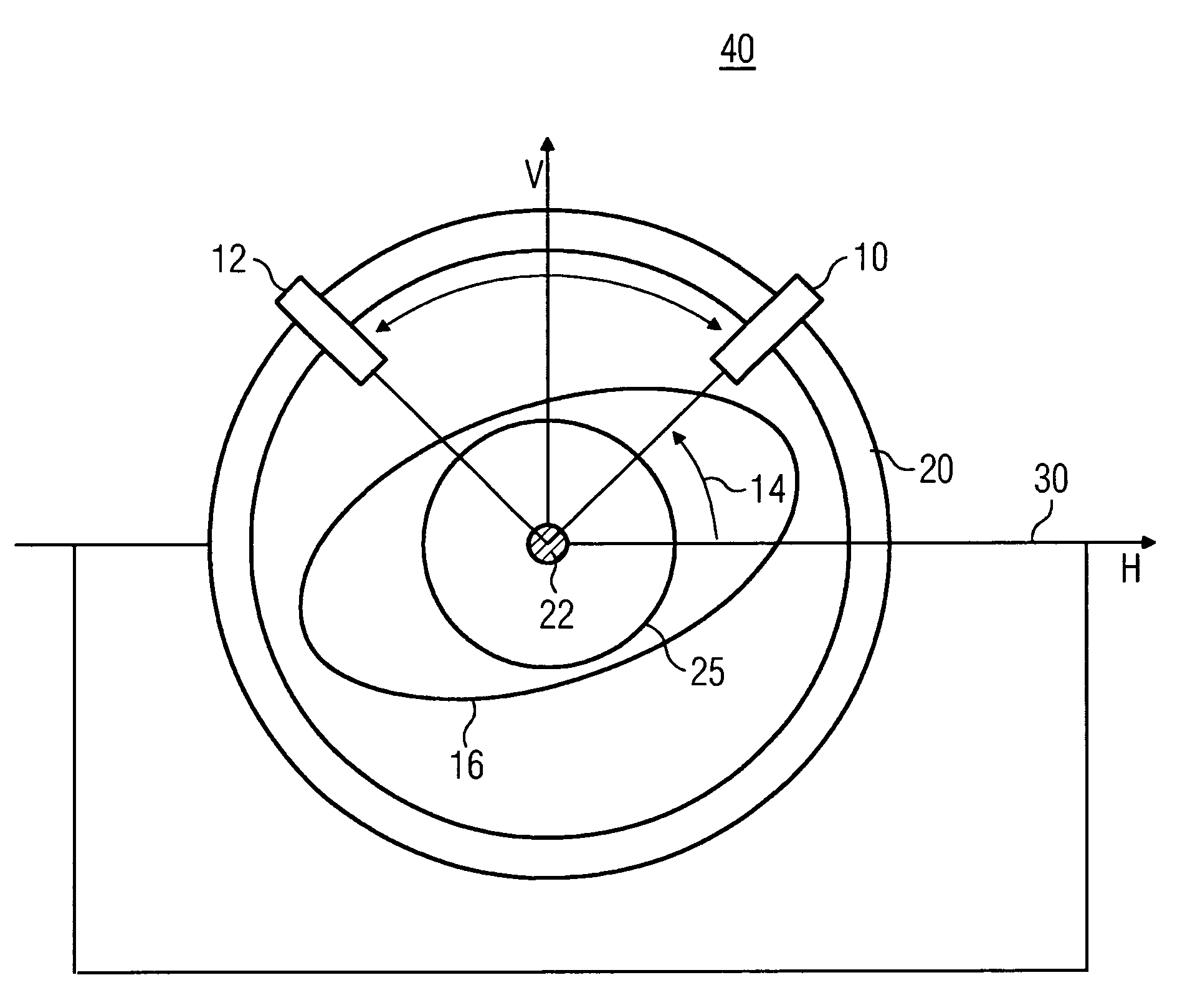
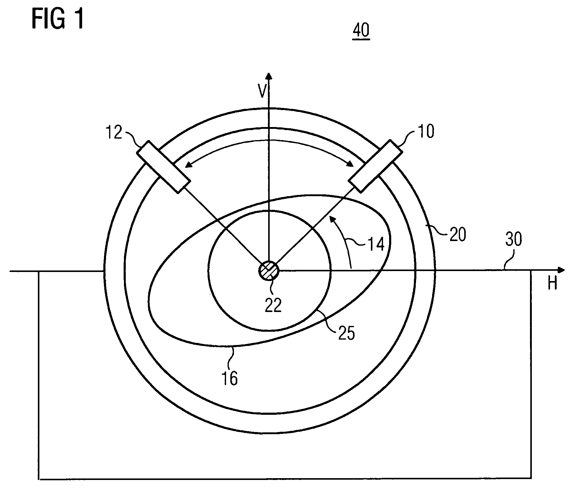
[0016]FIG. 1 shows a bearing housing 30, which is attached to a chassis 30 and which further features a turbine shaft 25. Attached to the bearing housing 30 are two sensors 10, 12 preferably spaced at a 90 degree angle from each other.

[0017]The machine 40 in this case features two main stiffness axes V, H (orthotropic coordinate system), which in this exemplary embodiment are shown as the vertical direction V and the horizontal direction H. The main stiffness axes V, H coincide with the vertical direction V and the horizontal direction H. The sensors are built in at an angle of β, 14, to the axis H.

[0018]Because of expansion joints for example it is not possible for the sensors to be positioned at any position on the bearing housing 30. Thus the sensors 10, 12 can for example not be mounted in the direction of the stiffness axes V, H of the machine 40. The rotation of the turbine shaft 25 now triggers vibrations. If these exceed a specific limit value there is a danger of the machin...


PUM


Abstract

The invention relates to a method for monitoring the dynamic behavior, in particular of the oscillating behavior of a rotating shaft, the oscillation being detected by at least two sensors at defined different spatial position, the oscillating behavior in at least one preferred direction being determined from the oscillation. The invention also relates to a device for monitoring oscillating behavior in a rotary machine with rotable parts, having at least two sensors, a shaft and a computing unit, characterized in that the at least two sensors are positioned in a defined spatial position outside the shaft, detect measurement variables which characterize the oscillations and are connected to a computing unit for the transfer of data. The invention also relates to a gas turbine and a steam turbine that use a method and a device as per the invention.

Description

CROSS REFERENCE TO RELATED APPLICATIONS[0001]This application is the US National Stage of International Application No. PCT / EP2006 / 064939, filed Aug. 2, 2006 and claims the benefit thereof. The International Application claims the benefits of European application No. 05018868.9 filed Aug. 31, 2005, both of the applications are incorporated by reference herein in their entiretyFIELD OF INVENTION[0002]The invention relates to a method for monitoring the dynamic behavior, especially of the vibration behavior of a rotating shaft. The invention further relates to a device which especially guarantees the execution of the method.BACKGROUND OF THE INVENTION[0003]The power generated in a rotating part of a machine, for example in a steam or gas turbine system, is becoming ever higher. With a steam turbine for example, this goes hand in hand with the increase in weight of the rotor and the increase in the distance between the centers. The increased vibrations associated with this are becoming...

Claims


Application Information

Patent Timeline
Patent Type & Authority Patents(United States)
IPC IPC(8): G01M15/14
CPCG01H1/003
Inventor BOETIUS, JOACHIMBORGER, THOMASSIEBERLING, HANS-GUNTHERTROCKEL, RAIMUND
Owner SIEMENS ENERGY GLOBAL GMBH & CO KG
Why Eureka
Try Eureka