
Enclosure apparatus and method

a technology of enclosure and apparatus, applied in the field of flexible enclosure apparatus, can solve the problems of not using pressure sensitive adhesives capable of forming, often generated dust and debris, etc., and achieve the effect of preventing harm and injury

Inactive Publication Date: 2012-03-20
GASMAN DANIEL T
View PDF24 Cites 12 Cited by
  • Summary
  • Abstract
  • Description
  • Claims
  • Application Information

AI Technical Summary

Benefits of technology

[0014]To alleviate the disadvantages and deficiencies of prior art devices and methods, the present invention provides a flexible enclosure apparatus which utilizes a pressure sensitive adhesive on its open end to adhere the enclosure apparatus to a selected work surface such as a building wall, vehicle body surface or the like and to form a secure seal between the enclosure apparatus and the selected surface which may be for example a building wall or ceiling. The pressure sensitive adhesive is an integral part of the enclosure apparatus and allows for secure adhesion to a work surface, yet is removable without damaging the work surface or leaving behind a residue. Furthermore, the pressure sensitive adhesive forms a seal with the work surface to help contain dust and debris generated within the enclosed work surface during operation and use.
[0016]In an embodiment of the invention, the open end of the enclosure apparatus body is flexible, allowing the opening to be adjusted to conform to the desired shape of the selected work surface. In another embodiment the open end is made rigid by the use of a frame, facilitating secure adhesion to relatively flat surfaces such as walls. The frame can help to maintain the enclosure apparatus body in an open position when mounted on a vertical surface such as a wall.
[0017]In a preferred embodiment of the invention, the enclosure apparatus body is constructed, at least in part, from a transparent polymeric material allowing the enclosed work surface to be easily observed.
[0018]A sealable slit is incorporated into the flexible enclosure apparatus body. This sealable slit allows easy access to the interior of the sealed enclosure body so that objects or materials can be added or removed as needed, or to allow access for items such as power cords, hoses, or tubing. The sealable slit also allows the interior of the enclosure to be viewed, for example if the visibility is obscured by a film of dust or debris on the interior of the enclosure apparatus body. As will be appreciated by one skilled in the art, the sealable slit can take a variety of forms. One particularly useful form for this slit is in the form of a standard zip-loc type closure having a slide although other closures such as those employing hook and loop fasteners could also be employed.

Problems solved by technology

Dust and debris are often generated during the repair, maintenance, rehabilitation, or renovation of various structures.
While these devices fulfill their particular objectives and requirements, the aforementioned devices do not utilize pressure sensitive adhesives capable of forming a seal with a work surface to thereby create an isolated work space for containing dust and debris generated therein.

Method used


Image

  • Enclosure apparatus and method
  • Enclosure apparatus and method
  • Enclosure apparatus and method

Examples


first embodiment

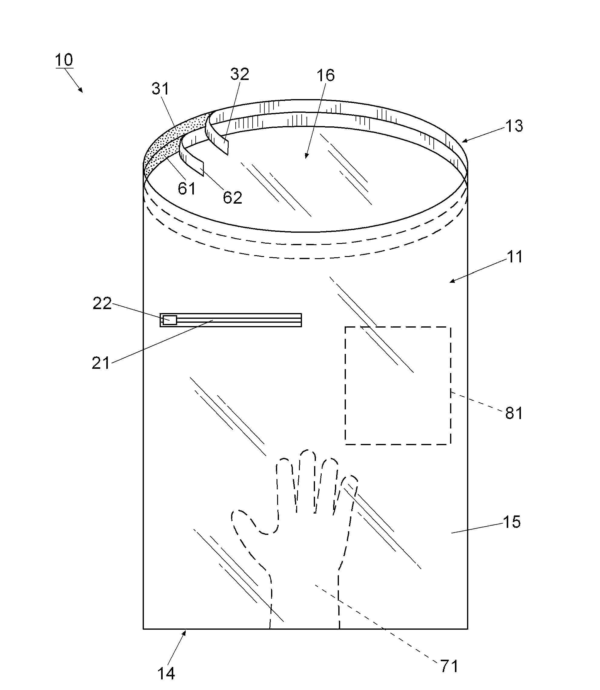
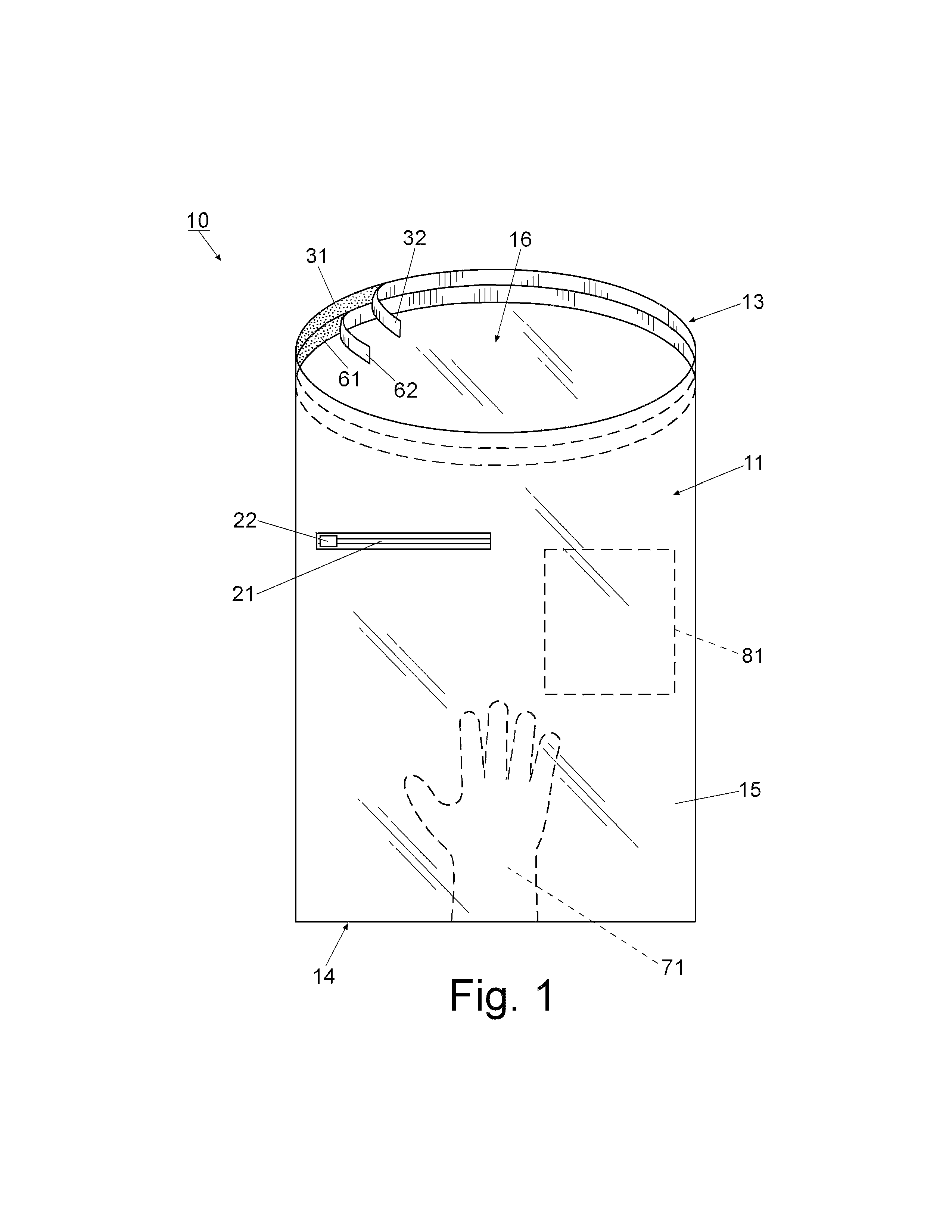
[0026]FIG. 1 shows the invention with body of enclosure apparatus 10 which consists of a flexible polymeric bag like structure. Body 11 is formed from a clear, transparent plastic such as a standard thin polyethylene material. Body 11 includes top 13, closed bottom 14 and side walls, generally at 15. At top opening 16 of body 11 pressure sensitive adhesive 31 is placed around the entire inside circumference of opening 16. Standard pressure sensitive adhesive 31 is used to adhere body 11 to a selected work surface and form a seal therebetween. Preferably pressure sensitive adhesive 31 is selected so that it provides adequate adhesion to the work surface, but is removable without damaging the work surface or leaving behind a residue. A typical release strip 32 is provided to preserve pressure sensitive adhesive 31 prior to use.

[0027]Enclosure body 11 includes a manual sealable slit 21 with closure slide 22 to allow easy access to the interior of body 11 once enclosure apparatus 10 has...

second embodiment

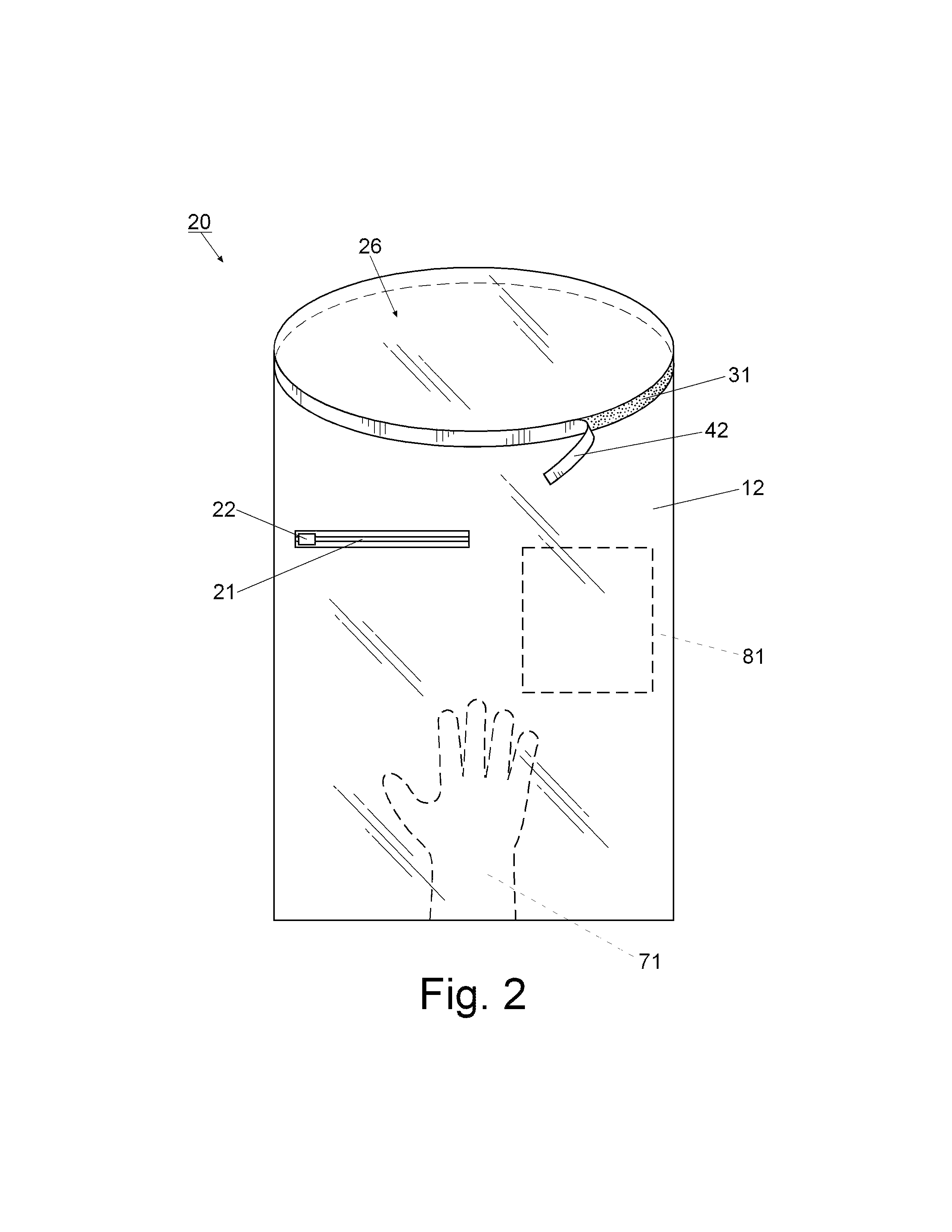
[0029]In FIG. 2 body 12 of a second embodiment, namely enclosure apparatus 20 is seen also consisting of a flexible bag like structure. Round top opening 26 of body 12 contains pressure sensitive adhesive 31 placed around the entire outer circumference of side walls 15, unlike the inner placement of adhesive 31 seen in FIG. 1. Pressure sensitive adhesive 31 is also used to adhere body 11 to a work surface (not seen in FIG. 2) and form a seal therebetween. Pressure sensitive adhesive 31 is selected so as to provide adequate adhesion between body 12 and the work surface, but is removable without damaging the work surface or leaving behind residue. Release strip 42 is provided to cover or shield pressure sensitive adhesive 31 prior to use. Body 12 also provides a manually sealable slit 21 with slide 22 to allow access as desired to the interior of body 12 once adhered to a work surface. Body 12 also optionally contains glove 71 to facilitate manipulation of objects or materials therewi...


PUM

PropertyMeasurementUnit
flexibleaaaaaaaaaa
pressureaaaaaaaaaa
transparentaaaaaaaaaa

Abstract

An enclosure apparatus for containing dust and debris such as may be generated while repairing a drywall surface. The enclosure apparatus includes a flexible, transparent body and may include a sealable slit, glove and pouch. The method of use allows the enclosure apparatus to be securely affixed to the drywall surface with a pressure sensitive adhesive. Tools or otherwise can be placed within the enclosure body prior to attachment to the drywall surface. Once the dust generating work is completed the enclosure apparatus can be removed, cleaned and properly disposed.

Description

FIELD OF THE INVENTION[0001]The present invention relates to an improved method and apparatus for the creation of an isolated work environment. More particularly the invention relates to a flexible enclosure apparatus incorporating a pressure sensitive adhesive for adhering and sealing the apparatus to a work surface to contain dust and debris.DESCRIPTION OF THE PRIOR ART AND OBJECTIVES OF THE INVENTION[0002]Dust and debris are often generated during the repair, maintenance, rehabilitation, or renovation of various structures. This dust and debris frequently constitutes a nuisance, for example when dust is generated form drywall, lead paint or asbestos containing materials. There is a great need for work enclosures that are able to contain such dust and debris to prevent harm and injury.[0003]The use of glove bags is known in the prior art for the containment of dust and debris. Examples include U.S. Pat. No. 5,131,934 (Patel), U.S. Pat. No. 5,017,197 (McGuire), U.S. Pat. No. 5,520,...

Claims


Application Information

Patent Timeline
Patent Type & Authority Patents(United States)
IPC IPC(8): B24B55/10
CPCB08B15/026B24B7/182B24B55/10B24D15/00
Inventor GASMAN, DANIEL T.
Owner GASMAN DANIEL T
Learn More