Transmission lines applied to contact free slip rings

a technology of transmission lines and slip rings, applied in transmission, one-port network, waveguide devices, etc., can solve the problems of limited power and/or data rate transfer capability, mechanical failure, sparking,

Active Publication Date: 2012-03-20
VOXIS
View PDF10 Cites 86 Cited by
  • Summary
  • Abstract
  • Description
  • Claims
  • Application Information

AI Technical Summary

Problems solved by technology

Contact-type slip rings have numerous disadvantages including mechanical failure, sparking, noise introduction, limited power and / or data rate transfer capability, etc.
These systems therefore require manufacturing and alignment tolerances that are difficult to achieve in order to function properly.

Method used


Image

  • Transmission lines applied to contact free slip rings
  • Transmission lines applied to contact free slip rings
  • Transmission lines applied to contact free slip rings

Examples


Embodiment Construction

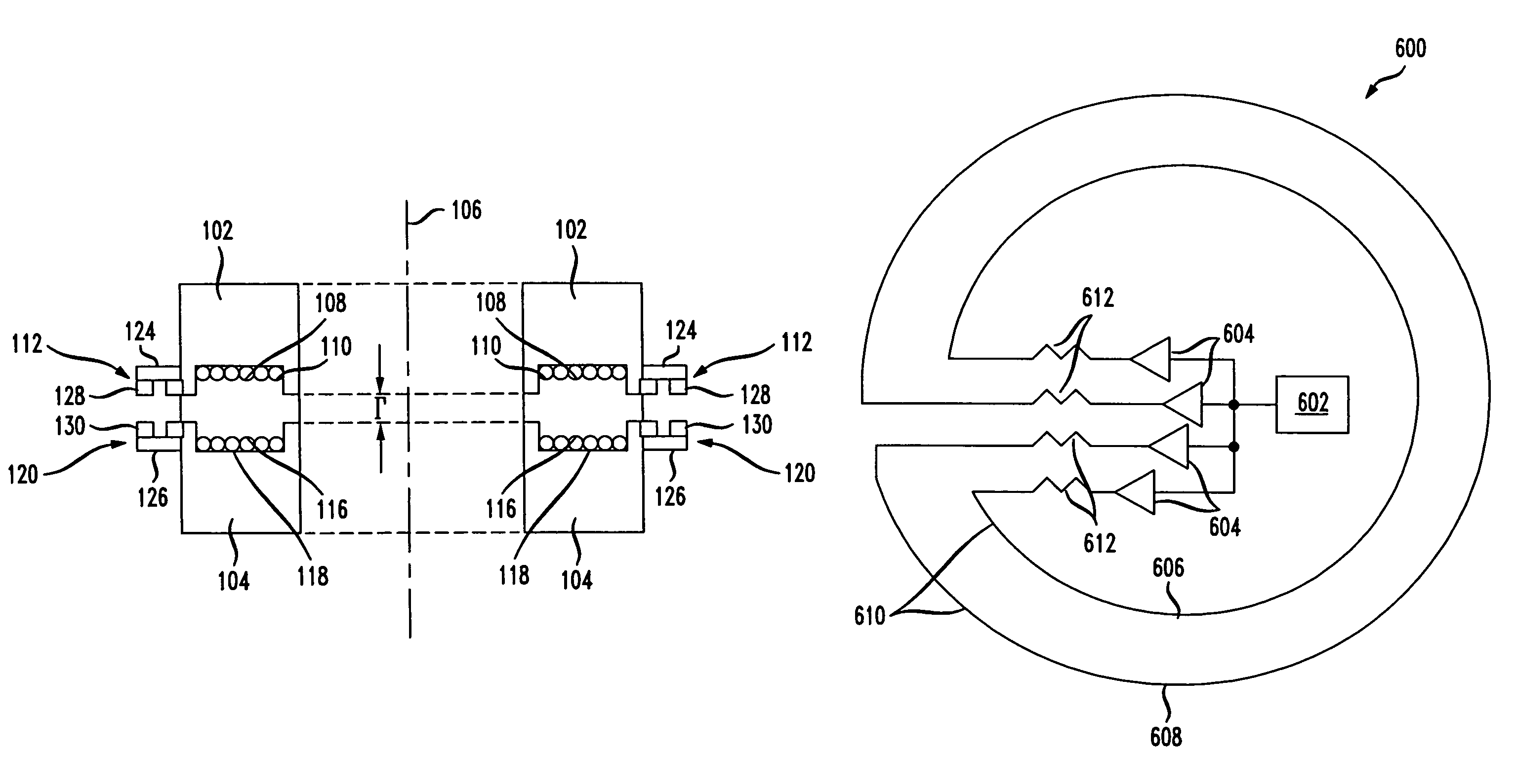
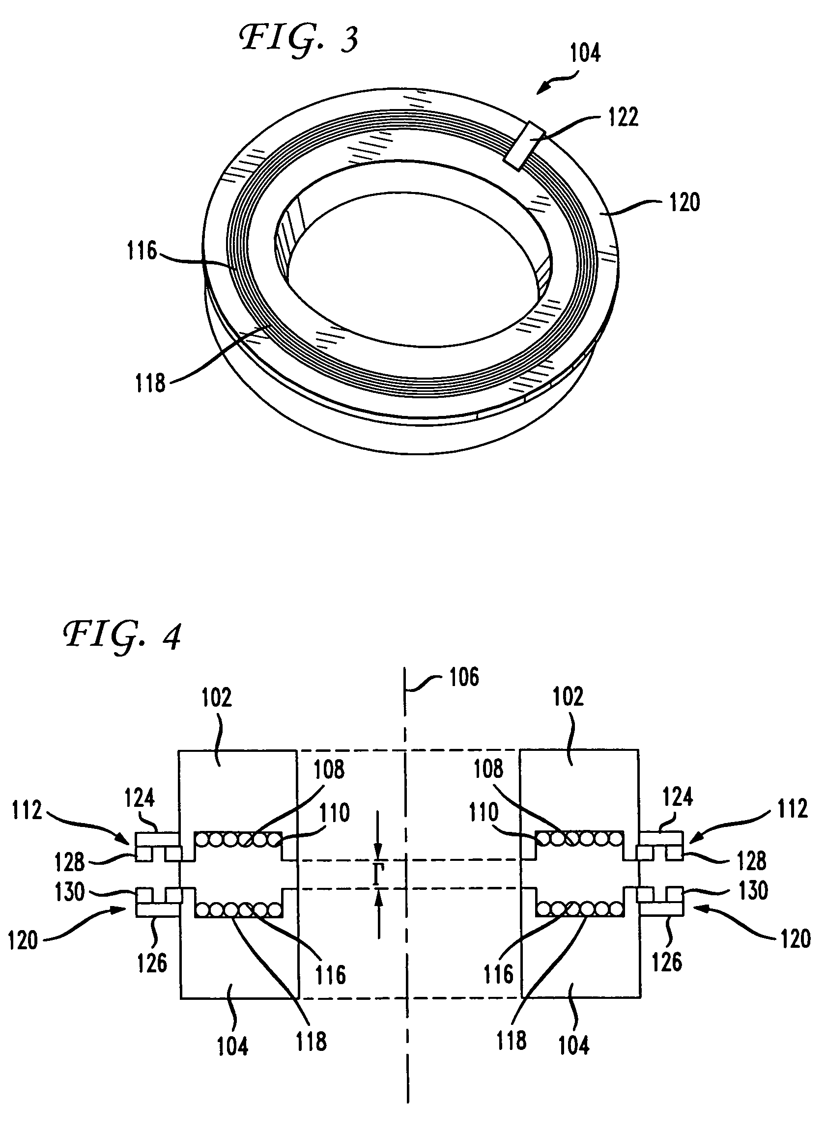
[0019]At least one embodiment of the present invention provides a rotary interface utilizing transmission lines to transmit information across a gap between a rotating and a non-rotating portion of the interface. Though described herein in terms of the exemplary embodiments shown in FIGS. 1-4 and FIG. 8, any appropriate layout or implementation of a rotary interface (e.g., contract free slip ring, etc.) may be used. For descriptive simplicity and clarity, rotary interfaces similar to a rotor-stator interface or a rotary transformer are described below. The various aspects and components of a generic rotary interface are not described in detail herein except as necessary to describe the present invention. One of skill in the art will recognize the various components and their uses that are omitted or briefly mentioned.

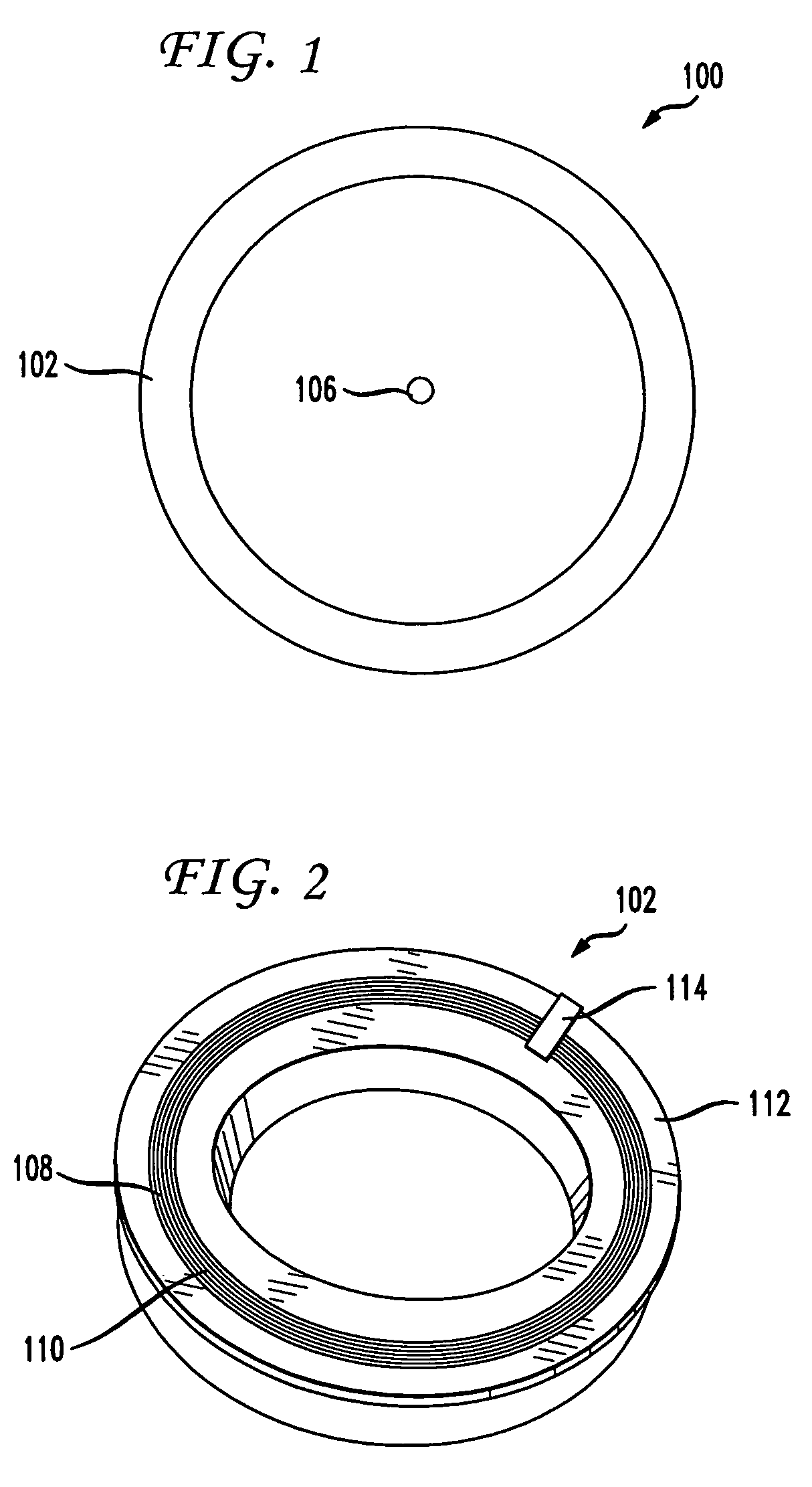
[0020]FIG. 1 depicts a top view of a rotary interface 100 according to an embodiment of the present invention. In at least one embodiment, rotary interface 100 comprise...


PUM


Abstract

A non-contacting rotary interface has a first core with a first pair of balanced transmission lines coupled to the first core and a second core moveable in relation to the first core with a second pair of balanced transmission lines coupled to the second core and configured to receive signals from the first pair of balanced transmission lines. The first pair of balanced transmission lines has a first transmit wire coupled to a first transceiver at a first end of the first transmit wire, a second transceiver coupled to the first transmit wire at a second end of the first transmit wire, a second transmit wire coupled to a third transceiver at a first end of the second transmit wire, and a fourth transceiver coupled to the second transmit wire at a second end of the second transmit wire. The balanced transmission lines may be electrical traces on a circuit board.

Description

[0001]This application claims the benefit of U.S. Provisional Application No. 60 / 994,564 filed Sep. 20, 2007, which is incorporated herein by reference.BACKGROUND OF THE INVENTION[0002]The present invention relates generally to signal transmission in non-contacting interfaces and more particularly to power and information transfer in non-contacting interfaces.[0003]Many systems require power and / or information to be transferred between surfaces in motion, such as between rotating surfaces. Generally, this is accomplished using contacting or non-contacting slip rings (e.g., rotary transformers, rotary electrical interfaces, rotating electrical connectors, collectors, swivels, electrical rotary joints, etc.). The slip ring system couples electrical signals between two portions of the slip ring that rotate in relation to each other.[0004]A contact-type slip ring generally consists of a conductive circle or band mounted on a shaft and insulated from it. The rotating portion of the syste...

Claims


Application Information

Patent Timeline
Patent Type & Authority Patents(United States)
IPC IPC(8): H01P5/02
CPCH04B5/00H04B5/0087H04B5/0037H01P1/068
Inventor WEST, JOSEPH NEWHALLKISER, JON ROBERTDIMSDALE, JERRY SAMUEL
Owner VOXIS
Why Eureka
Try Eureka