
Creating references in a scoped memory system

a reference and memory system technology, applied in the field of scoped memory system reference creation, can solve the problems of time-consuming iterations, and achieve the effect of reducing processing overhead during the creation of referen

Inactive Publication Date: 2012-03-20
INT BUSINESS MASCH CORP
View PDF3 Cites 4 Cited by
  • Summary
  • Abstract
  • Description
  • Claims
  • Application Information

AI Technical Summary

Benefits of technology

This approach reduces processing overhead during reference creation by eliminating the need for arduous iterations through the scope graph, ensuring compliance with the single parent rule while maintaining efficient memory management.

Problems solved by technology

However, since individual scoped memory areas can become completely discardable it is necessary to enforce strict rules regarding valid and invalid references between objects in different scoped memory areas.
While these approaches may be effective in applying the criterion for the creation of new references, they involve time consuming iterations through a scope graph at the point of reference creation.

Method used


Image

  • Creating references in a scoped memory system
  • Creating references in a scoped memory system
  • Creating references in a scoped memory system

Examples


Embodiment Construction

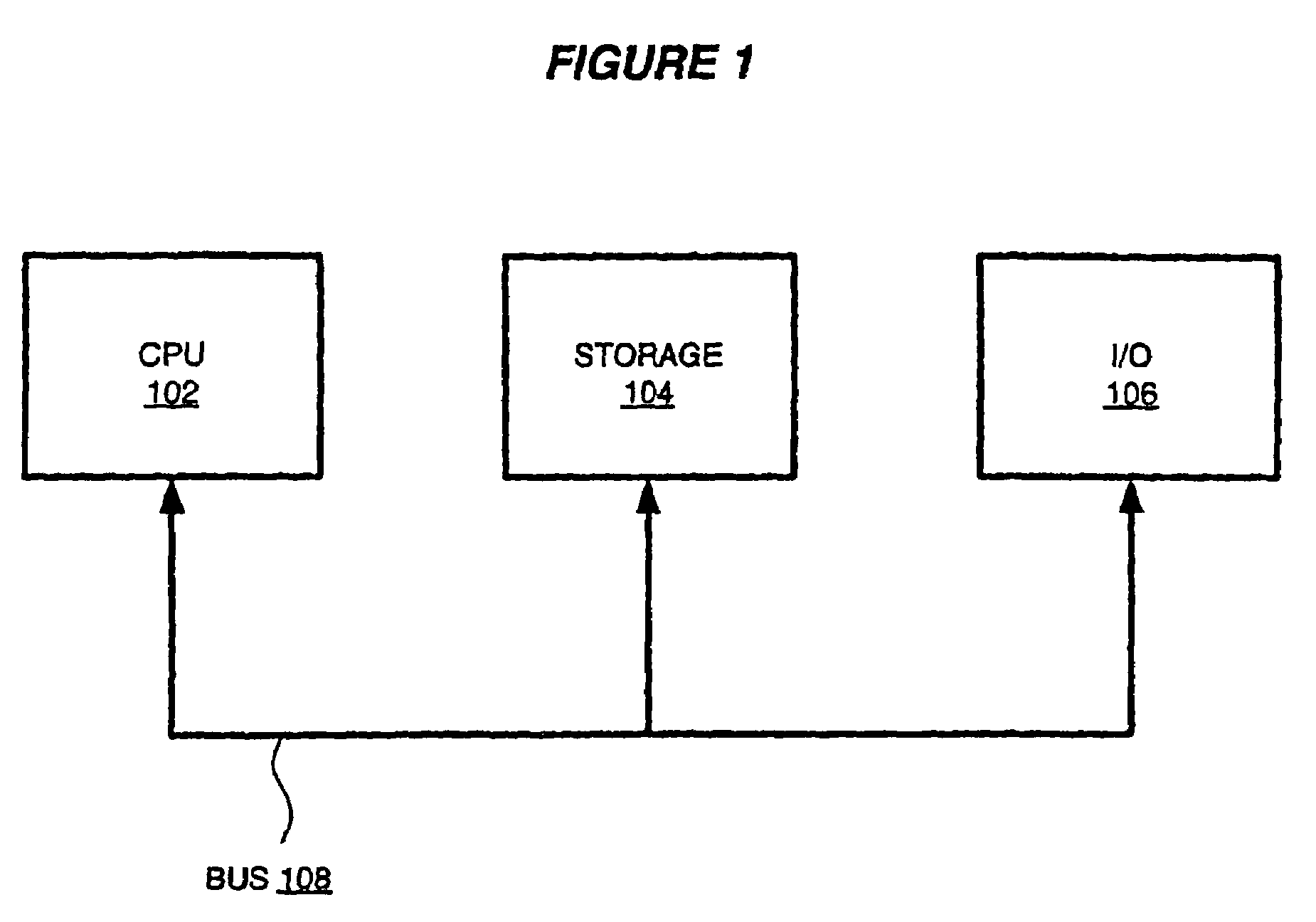
[0024]FIG. 1 is a block diagram of a computer system suitable for the operation of embodiments of the present invention. A central processor unit (CPU) 102 is communicatively connected to a storage 104 and an input / output (I / O) interface 106 via a data bus 108. The storage 104 can be any read / write storage device such as a random access memory (RAM) or a non-volatile storage device. An example of a non-volatile storage device includes a disk or tape storage device. The I / O interface 106 is an interface to devices for the input or output of data, or for both input and output of data. Examples of I / O devices connectable to I / O interface 106 include a keyboard, a mouse, a display (such as a monitor) and a network connection.

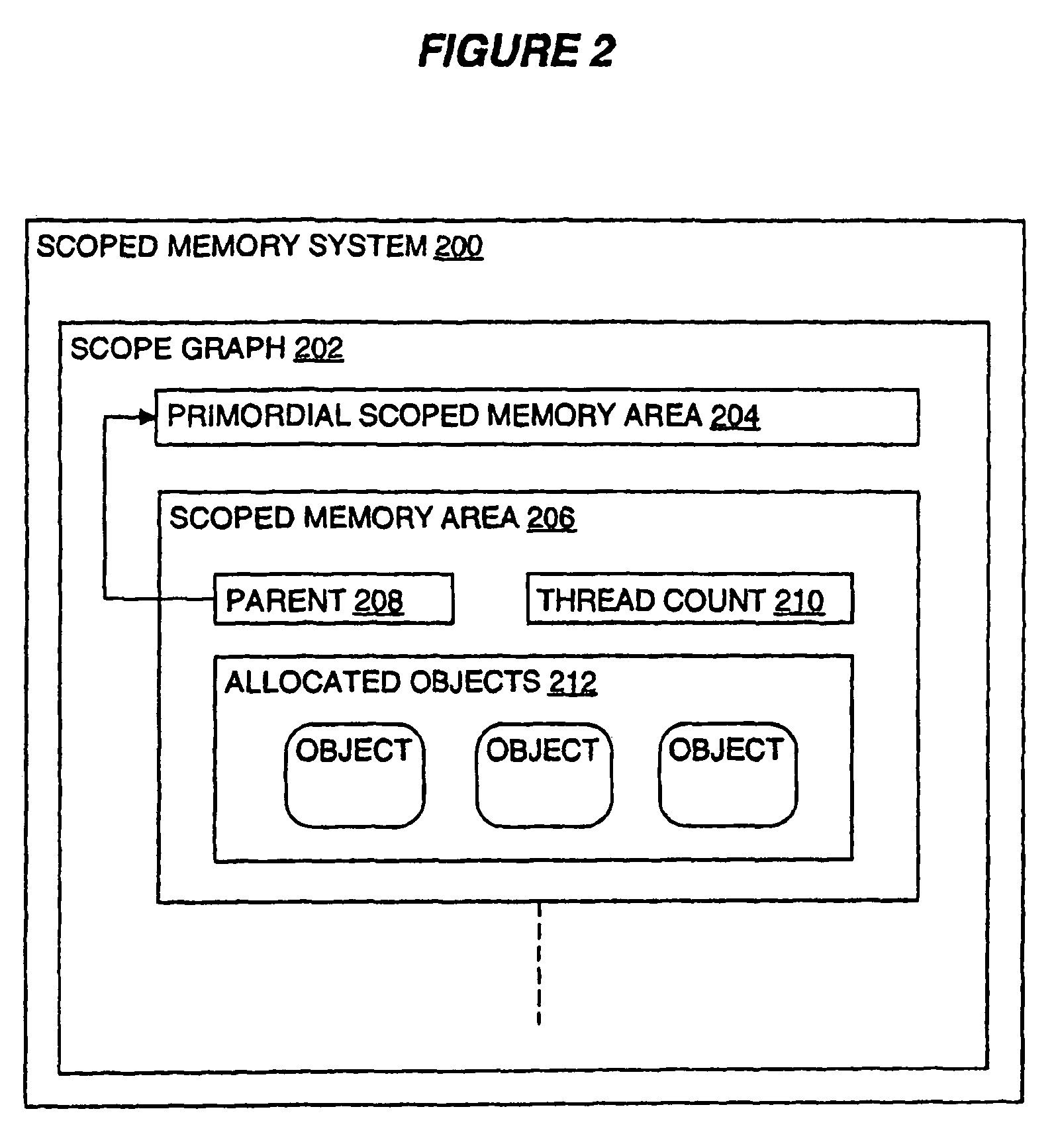
[0025]FIG. 2 is a block diagram of an exemplary scoped memory system 200 in accordance with a preferred embodiment of the present invention. The scoped memory system is an arrangement of a part of a storage 104 of a computer system such as the scoped memory system d...


PUM


Abstract

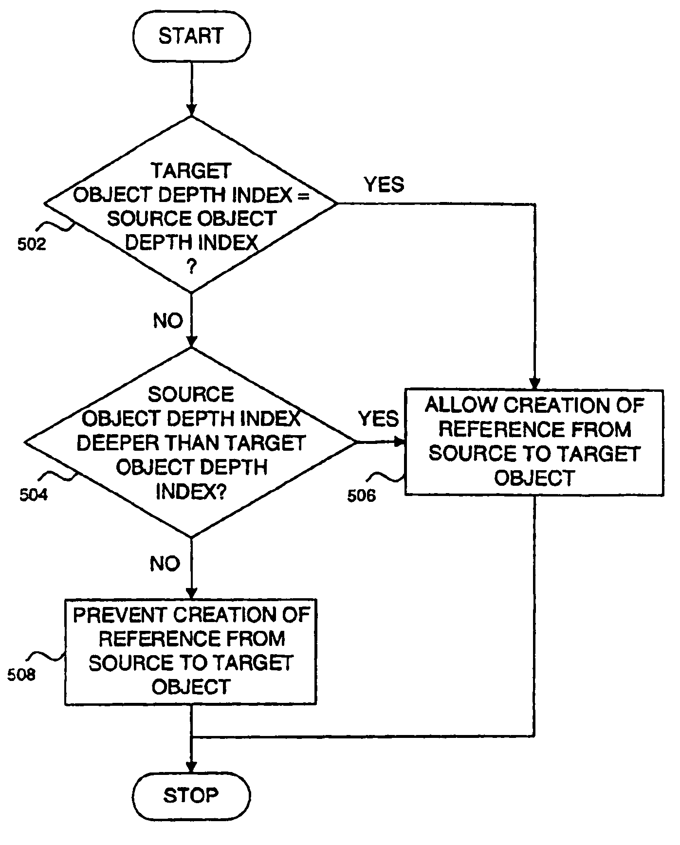
A method for creating a reference in a scoped memory system, the scoped memory system including a scope graph of scoped memory areas, wherein each scoped memory area is suitable for the allocation of objects therein for access by software threads and has associated a thread count for indicating that the scoped memory area is discardable, the method comprising the steps of: allocating a target object in a target scoped memory area; storing an index associated with the target object of a depth of the target scoped memory area in the scope graph; allocating a source object in a source scoped memory area; storing an index associated with the source object of a depth of the source scoped memory area in the scope graph; in response to a determination that the source scoped memory area is at the same depth as or deeper than the target scoped memory area by comparing the index associated with the source object and the index associated with the target object, creating a reference from the target object to the source object.

Description

FIELD OF THE INVENTION[0001]The present invention relates to the creation of a reference in a scoped memory system. More particularly it relates to reducing processing overhead during the creation of a reference.BACKGROUND OF THE INVENTION[0002]Scoped memory areas are areas of memory suitable for the allocation and deallocation of objects without some of the disadvantages of garbage collected heaps. A software thread can enter a scoped memory area and all object allocations by the thread will then be made within the scoped memory area. The thread can also enter multiple scoped memory areas in a nested fashion. For example, the thread can enter a second scoped memory area which becomes the default allocation area. Scoped memory areas are organised in a scope graph with each scoped memory area having a parent being the previously entered scoped memory area. A first scoped memory area has a primordial scoped memory area as its parent.[0003]A thread count is maintained for each scoped m...

Claims


Application Information

Patent Timeline
Patent Type & Authority Patents(United States)
IPC IPC(8): G06F12/00G06F17/30
CPCG06F12/0261
Inventor JOHNSON, ANDREW
Owner INT BUSINESS MASCH CORP
Learn More