
Multi-impact hand tool

a multi-impact, hand tool technology, applied in the direction of percussive tools, manufacturing tools, portable drilling machines, etc., can solve the problems of suffering from over-the-counter multi-impact hand tools, and achieve the effect of improving working efficiency and improving working efficiency

Inactive Publication Date: 2012-03-27
SU CHENG WEI
View PDF6 Cites 17 Cited by
  • Summary
  • Abstract
  • Description
  • Claims
  • Application Information

AI Technical Summary

Benefits of technology

[0008]The primary objective of the present invention is to provide a multi-impact hand tool which can provide a multi-impact effect through only one impact operation to improve the working efficiency and can make the impact force be directly transferred to a tool head to perform the chiseling operation to improve the working efficiency.

Problems solved by technology

However, the above conventional multi-impact hand tool suffers from the following drawbacks.

Method used


Image

  • Multi-impact hand tool
  • Multi-impact hand tool
  • Multi-impact hand tool

Examples


Embodiment Construction

[0019]The present invention will be clearer from the following description when viewed together with the accompanying drawings, which show, for purpose of illustrations only, the preferred embodiment in accordance with the present invention.

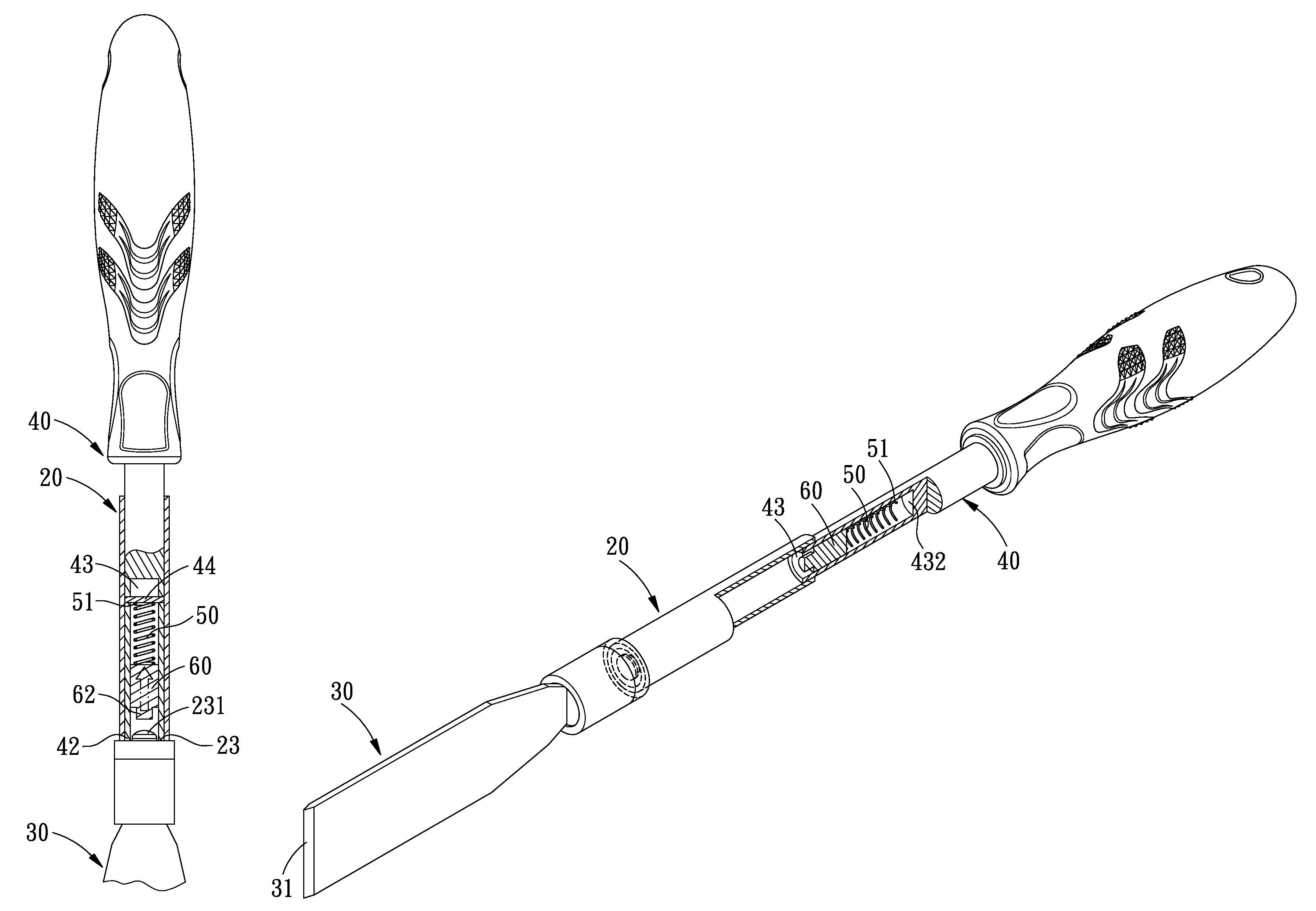
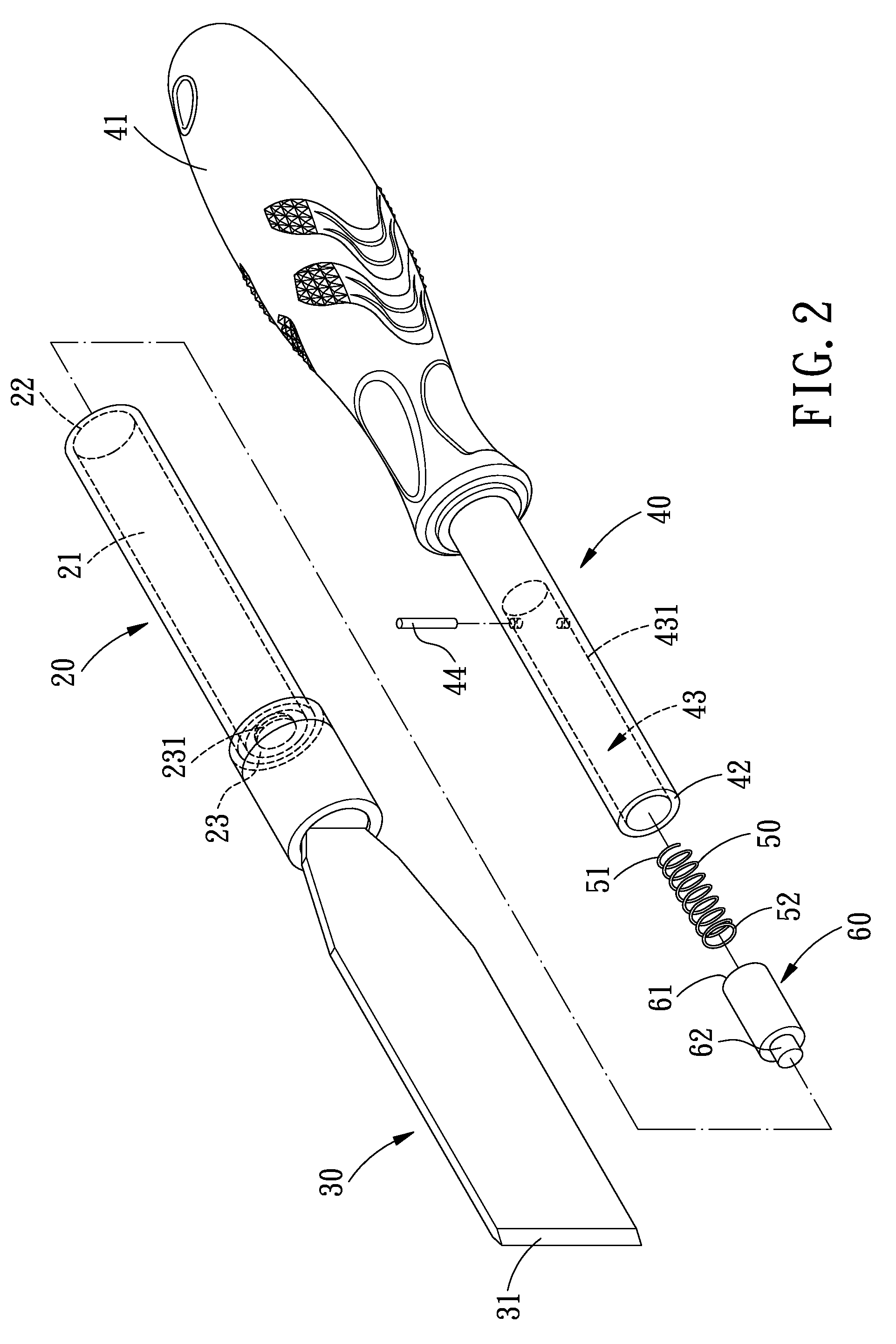
[0020]Referring to FIGS. 2-4, a multi-impact handle tool in accordance with a preferred embodiment of the present invention essentially comprises a sleeve 20, a tool head 30, a movable rod 40, a spring 50 and an impact block 60.

[0021]The sleeve 20 is a hollow structure defined with an axial hole 21. The axial hole 21 includes an open end 22 and a closed end 23 that are oppositely arranged. The closed end 23 seals an interior of the axial hole 21 and is centrally formed with a protrusion 231 protruding toward the open end 22.

[0022]The tool head 30 has one end connected to the closed end 23 of the sleeve 20, and the other end of the tool head 30 is a working end 31. The working end 31 is formed into a desired shape, and in the present embodiment, i...


PUM

PropertyMeasurementUnit
elastic forceaaaaaaaaaa
chiseling forceaaaaaaaaaa
shapeaaaaaaaaaa

Abstract

A multi-impact hand tool comprises a sleeve, a tool head, a movable rod, a spring and an impact block. With only one impact operation, the multi-impact hand tool can provide a multi-impact effect, thus improving the working efficiency. In addition, the impact force can be directly transferred to the tool head for performing the chiseling operation, thus improving the working efficiency.

Description

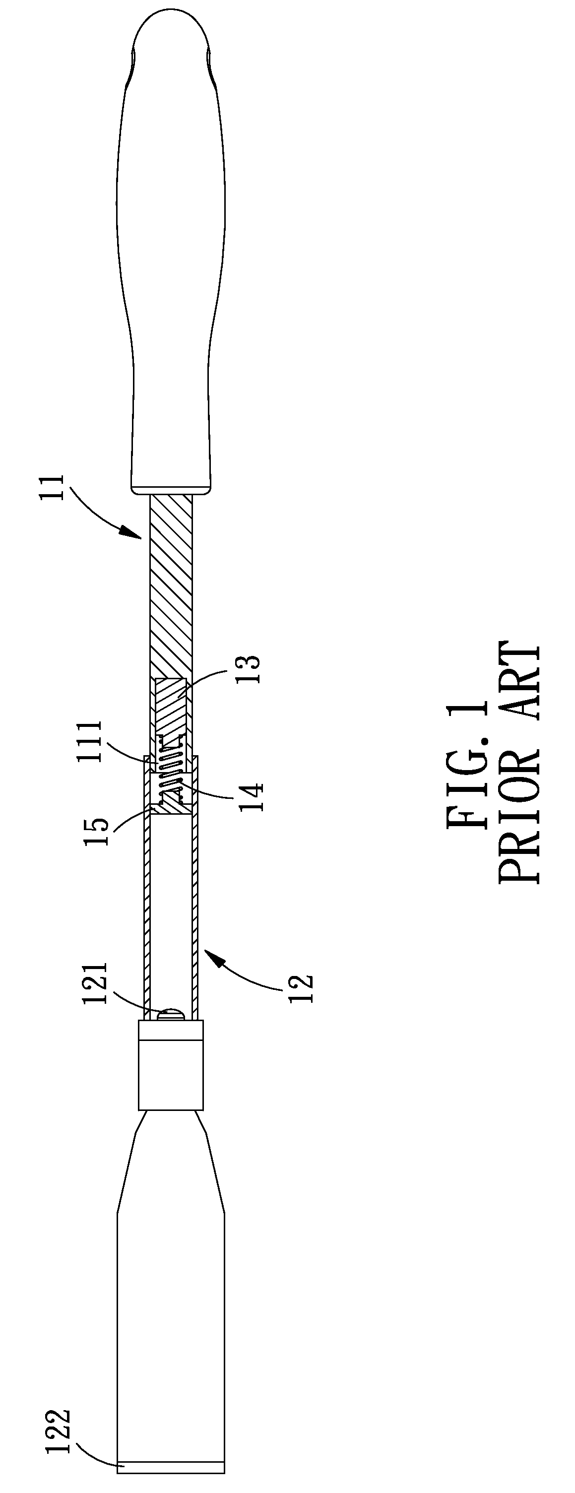
BACKGROUND OF THE INVENTION[0001]1. Field of the Invention[0002]The present invention relates to an impact hand tool, and more particularly to a multi-impact hand tool.[0003]2. Description of the Prior Art[0004]Referring to FIG. 1, a conventional multi-impact hand tool essentially comprises an impact rod 11 with a movable pipe 12 engaged thereon. Between the impact rod 11 and the movable pipe 12 is disposed an assistant impact assembly including an assembling block 13, a spring 14 and an impact block 15.[0005]By such arrangements, the user can hold the movable pipe 12 with one hand while pulling the impact rod 11 with the other to move the impact block 15 away from the distal end 121 of the movable pipe 12, and subsequently releasing the impact rod 11 to allow it to drive the impact block 15 to impact against the distal end 121 of the movable pipe 12 to make the tool head 122 at the front end of the movable pipe 12 perform a chiseling operation. In addition, when the impact block 15...

Claims


Application Information

Patent Timeline
Patent Type & Authority Patents(United States)
IPC IPC(8): B25D3/00B25D1/16
CPCB25D3/00B25D2250/241B25D2250/371
Inventor SU, CHENG-WEI
Owner SU CHENG WEI
Learn More