Instrument for use in a joint replacement procedure

a joint replacement and instrument technology, applied in the field of instruments for use in joint replacement procedures, can solve the problems of inconvenient use, wear of bearing surfaces, inconvenient alignment,

Active Publication Date: 2012-03-27
DUPUY INT LTD
View PDF12 Cites 18 Cited by
  • Summary
  • Abstract
  • Description
  • Claims
  • Application Information

AI Technical Summary

Benefits of technology

[0026]It can be preferred for the parts of the instrument of the invention to be coloured. It is an advantage of polymeric materials in the pre...

Problems solved by technology

Inappropriate alignment can give rise to post-operative problems, including limited range of motion of the joint, ...

Method used


Image

  • Instrument for use in a joint replacement procedure
  • Instrument for use in a joint replacement procedure
  • Instrument for use in a joint replacement procedure

Examples


Embodiment Construction

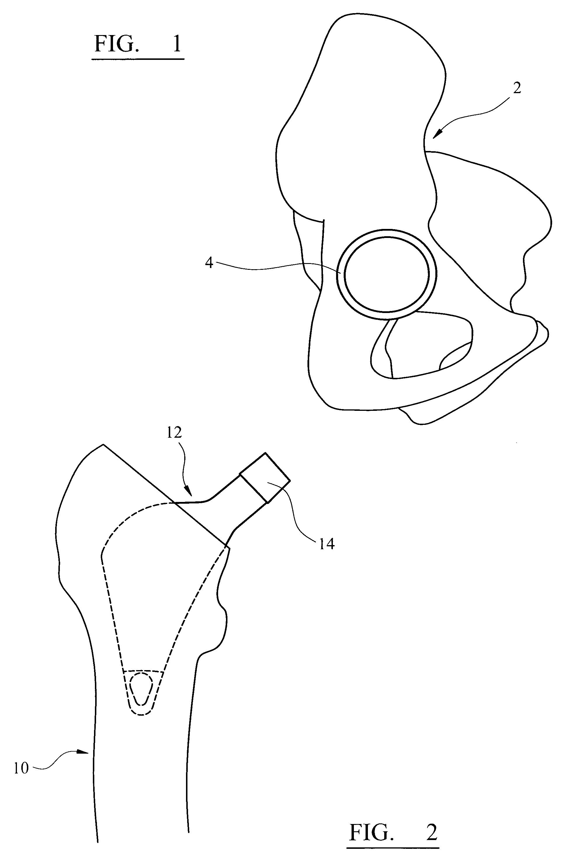
[0042]Referring to the drawings, FIG. 1 shows a pelvis 2 which is been reamed to receive the acetabular cup component 4 of a hip joint prosthesis. The acetabular cup component has been implanted using conventional techniques.

[0043]FIG. 2 shows the head portion of a femur 10 which has been resected at the base of the femoral neck. The intramedullary cavity has been prepared using conventional techniques (by reaming or broaching or a combination of the two) to receive the stem part 12 of the femoral component of a hip joint prosthesis. The stem part can be fastened in the femur by means of a bone cement material, as is known. The stem part can be fastened in the femur without the use of a bone cement material, as is known.

[0044]The stem part has a tapered spigot 14 at its exposed end on which the head part of the femoral component can be fitted. The dimensions of the spigot on the stem part are in line with existing stem parts of femoral components of hip joint prostheses.
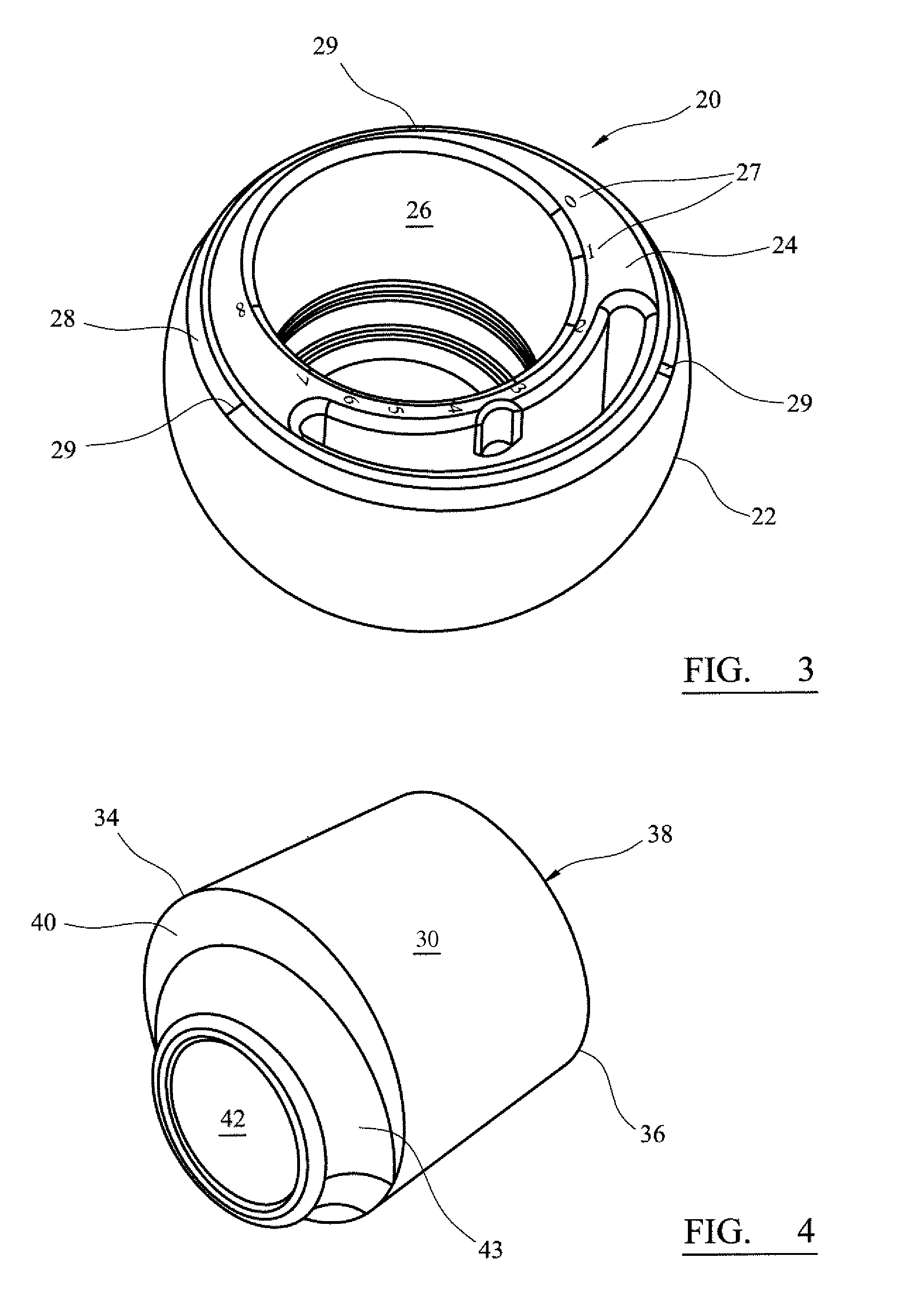
[0045]FIG. 3...


PUM


Abstract

An instrument for use in a joint replacement procedure comprises a head part which corresponds to the head of an orthopaedic joint component, in which the head part has a bore formed in it, and a connector for connecting the head part to a stem part of the orthopaedic joint component, which is intended for location in the intramedullary cavity of a bone. The connector can be fitted into the bore in the head part in one of a plurality of angular orientations. It comprises a body part and a trigger which can be moved relative to the body part between an unlocked position in which the connector can be moved relative to the head part between different ones of the plurality of angular orientations and a locked position in which the connector is restrained against such movement.

Description

CROSS REFERENCE TO RELATED APPLICATION[0001]This application is a National Stage 35 U.S.C. 371 of International Patent Application PCT / GB2008 / 001055 filed on Mar. 27, 2008.BACKGROUND OF INVENTION[0002]This invention relates to an instrument for use in a joint replacement procedure.[0003]The success of a joint replacement procedure depends in part on the appropriate alignment of the articulating parts of the joint prosthesis. Inappropriate alignment can give rise to post-operative problems, including limited range of motion of the joint, wear of the bearing surfaces which is uneven or excessive, and damage to soft tissue which is associated with the joint.[0004]it is known to construct the humeral component of a shoulder joint prosthesis using a stem part, a head part, and a connector part which can be fitted into a bore in the head part, and has a bore formed in it to receive a spigot on the stem part. Such a device is disclosed in US-A-2005 / 0197708. The eccentric arrangement of the...

Claims


Application Information

Patent Timeline
IPC IPC(8): A61F2/30
CPCA61F2/4637A61F2/4684A61F2/36A61F2/40A61F2002/30332A61F2002/305A61F2002/30537A61F2002/30617A61F2220/0025A61F2220/0033A61F2250/0004A61F2250/0097A61F2310/00011A61F2310/00179A61F2310/00353
Inventor BROOKS, JAMESGOWERS, STEVENTHOMPSON, JONATHAN
Owner DUPUY INT LTD
Why Eureka
Try Eureka