Input device and electronic apparatus using same

a technology of input device and electronic apparatus, applied in the field of input device, can solve the problems of limited thinning and miniaturization of input device, abnormal noise caused by external vibration etc., and achieve the effect of reducing the number of input devices

Inactive Publication Date: 2012-03-27
ORMON CORP
View PDF19 Cites 65 Cited by
  • Summary
  • Abstract
  • Description
  • Claims
  • Application Information

AI Technical Summary

Benefits of technology

[0006]However, in the above-described multi-direction input device, the collar part 11b of the operation body 11 needs to be incorporated in the hole 10c of the drive body 10, and the operation body 11 needs to be slidably moved to operate. Thus, a gap in a vertical direction and a horizontal direction constantly is formed between the collar part 11b and the hole 10c. As a result, not only is thinning and miniaturization of the input device limited, but tilt and rattling occur in the operation body 11, and an abnormal noise caused by external vibration etc. tends to easily occur.
[0007]If the gap in the vertical direction is too small, the operation body 11 is pressed against the drive body 10 in a deformation that occurs when an external force is applied to a housing 12, and malfunction may occur. If the height dimension of the hole 10d of the drive body 10 and the thickness dimension of the collar part 11b of the operation body 11 are increased to increase the opposing slidably moving area in order to reduce tilt and rattling of the operation body 11, thinning cannot be achieved, while wear tends to easily occur by the slidably moving operation in the vertical direction of the operation body 11, and therefore, the durability lowers.
[0008]One or more embodiments of the present invention provides a thin and miniaturized input device capable of preventing tilt and rattling of the operation member and preventing occurrence of abnormal noise by position-regulating the operation member using magnetic force of a magnet necessary for the input operation, and an electronic device using the same.

Problems solved by technology

As a result, not only is thinning and miniaturization of the input device limited, but tilt and rattling occur in the operation body 11, and an abnormal noise caused by external vibration etc. tends to easily occur.

Method used


Image

  • Input device and electronic apparatus using same
  • Input device and electronic apparatus using same
  • Input device and electronic apparatus using same

Examples


first embodiment

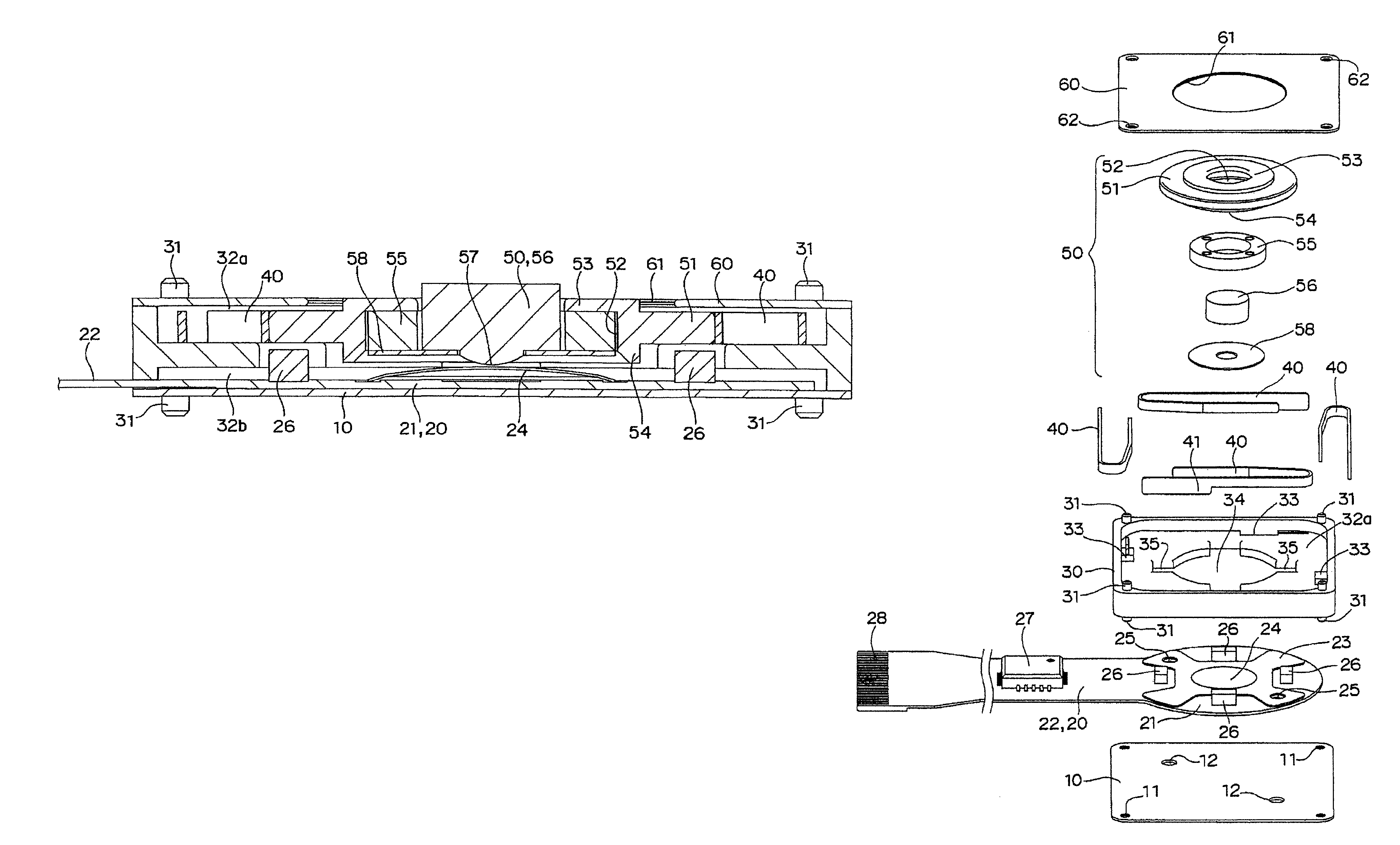
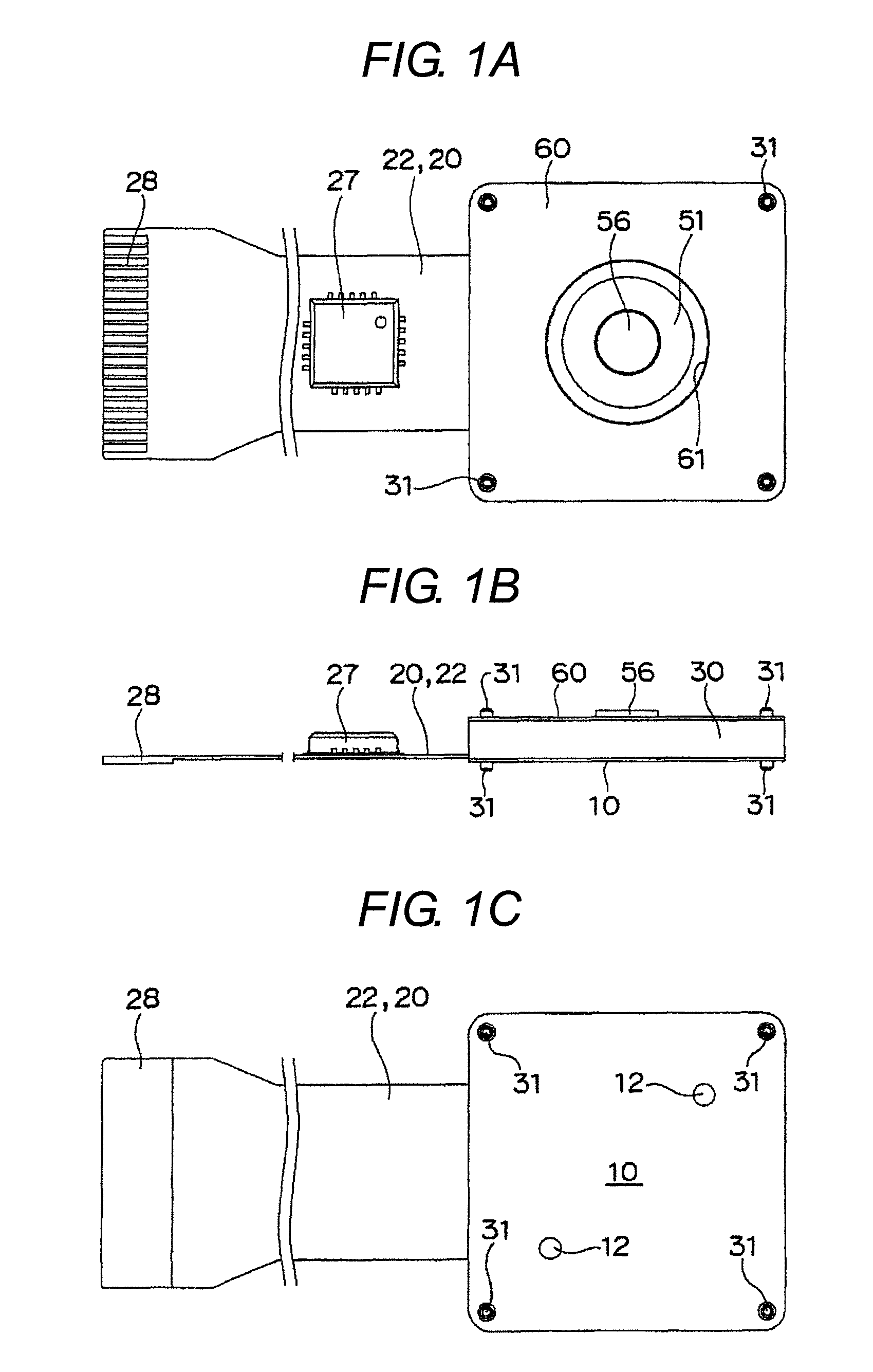
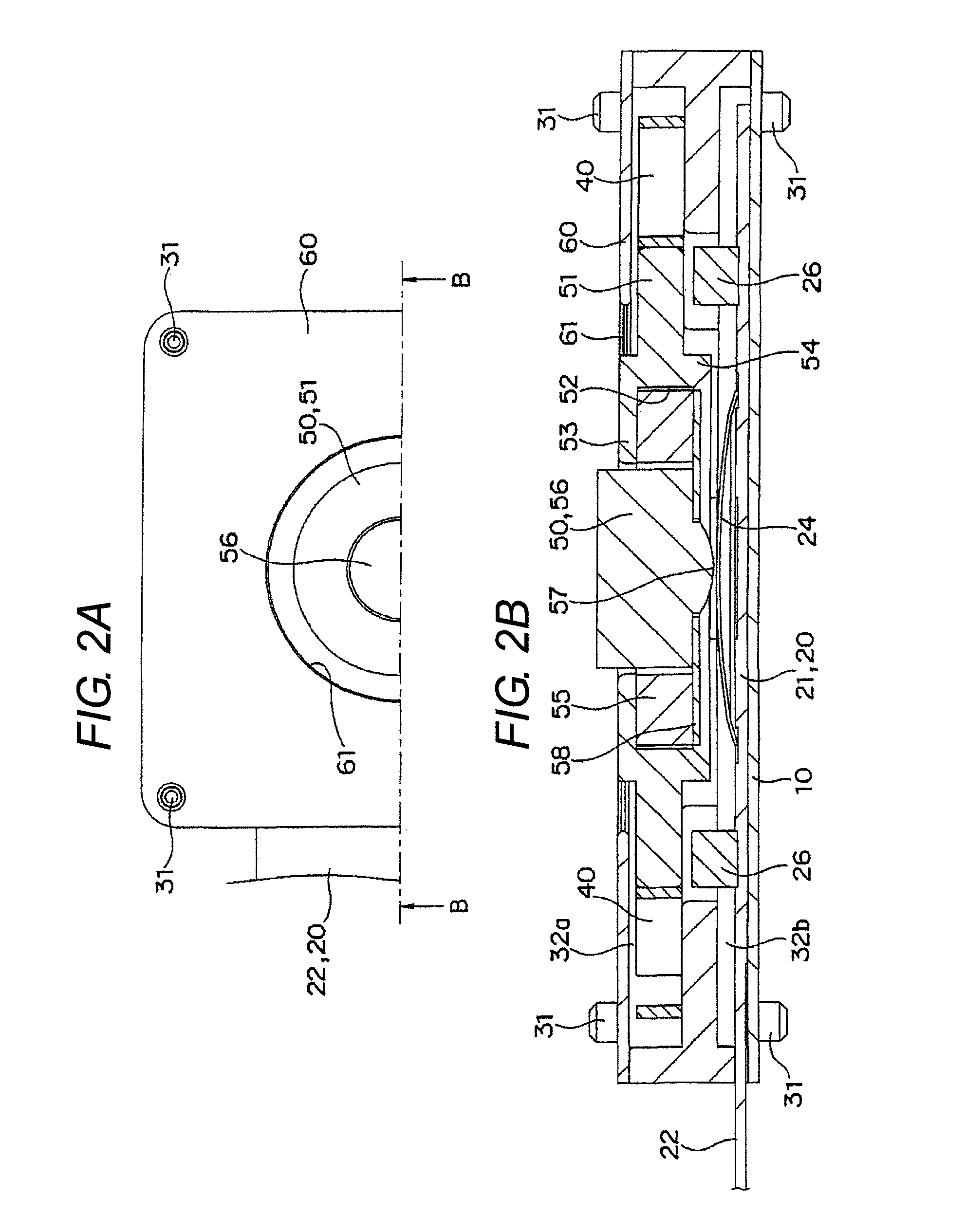
[0037]As shown in FIGS. 1A to 7C, the first embodiment includes a base plate 10, a flexible print substrate 20, a base 30, a position-regulation spring 40, an operation member 50, and a cover plate 60.

[0038]As shown in FIGS. 3 and 4, the base plate 10 is a metal thin plate having a substantially square shape in plane that includes a caulking hole 11 at the four corners and a jig hole 12 diagonally.

[0039]The flexible print substrate 20 has a lead portion 22 extending from a substantially circular print substrate main body 21 that can be mounted on the base plate 10. A dome sheet 23 having a substantially X-shape in plane is adhered and integrated to and with the print substrate main body 21, and a center push button switch 24 is formed at the central part and a jig hole 25 is formed. A Hall element 26 is mounted at the periphery of the dome sheet 23. A control IC 27 is mounted on the lead portion 22, and the lead portion 22 has a free end formed with a connecting portion 28.

[0040]As ...

second embodiment

[0055]As shown in FIGS. 8A to 8C, the second embodiment is a case where the central push button 56 and a disc plate portion 58a are integrally molded with a magnetic material.

[0056]According to the present embodiment, the number of parts and the number of assembly steps are reduced, and the productivity is enhanced.

[0057]In the first and second embodiments, if the polarity of the disc plate portion 58a is made the same polarity as the circular ring-like magnet 55, the central push button 56 can be position-regulated using the repulsive force thereof to thereby prevent tilt and rattling.

third embodiment

[0058]As shown in FIGS. 9A to 9C, the third embodiment is a case where the circular ring-shaped magnet 55 is integrally assembled to the central push button 56, the cover plate 60 is made of magnetic material, and the circular ring-shaped magnet 55 is adsorbed thereto.

[0059]According to the present embodiment, the holder is unnecessary, whereby the number of parts and number of assembly steps are reduced, the productivity is enhanced, and the input device can be further thinned and miniaturized.


PUM


Abstract

An input device has a housing having an operation hole formed therein, an operation member supported in a slidably moving manner in multi-directions within the operation hole, and at least two magnetic sensors, arranged at a periphery of the operation member, for detecting change in magnetic property by displacement of the operation member. The operation member includes a holder having a circular ring-shaped magnet incorporated in a fit-in hole and a central push button having a disc plate made of magnetic material integrated at a lower surface. The central push button is fitted in the circular ring-shaped magnet to adsorb, in a separable manner, the disc plate to the circular ring-shaped magnet and position-regulate the central push button.

Description

BACKGROUND OF THE INVENTION[0001]1. Technical Field[0002]The present invention relates to an input device used in an electronic device such as a portable telephone, PC, PDA, television, and videocassette recorder.[0003]2. Related Art[0004]Conventionally, the input device includes a multi-direction input device including an operation member held in a slidable manner in multi-directions, a plurality of movable contacts having conductivity arranged at an outer peripheral part of the operation member, and a plurality of insulating substrates, including a resistor body, arranged in a range of the operation member, where each of the plurality of movable contacts is arranged facing the plurality of resistor bodies, and the movable contact moves with the slidable movement of the operation member so that the contact area of the movable contact with respect to the resistor body varies.[0005]In such multi-direction input device, as shown in FIG. 1 of Japanese Unexamined Patent Publication No. ...

Claims


Application Information

Patent Timeline
Patent Type & Authority Patents(United States)
IPC IPC(8): H01H9/00G06F3/033G06F3/0338G06F3/0354
CPCH01H25/002H01H5/02H01H36/00H01H2025/004H01H25/041H01H13/14H01H13/26H01H13/48H04M1/23G06F3/033
Inventor WASHIZU, TOMOYUKIABEMIYASAKA, TAKESHIMUROTA, MASAYUKI
Owner ORMON CORP
Why Eureka
Try Eureka