Cleaning device and process for producing the same

a technology of cleaning device and heat sealing, which is applied in the direction of carpet cleaners, cleaning equipment, cleaning machines, etc., can solve the problems of long operating time, high cost, and difficulty in uniform and reliable heat sealing,

Inactive Publication Date: 2012-04-03
YAMADA KIKUO
View PDF20 Cites 68 Cited by
  • Summary
  • Abstract
  • Description
  • Claims
  • Application Information

AI Technical Summary

Benefits of technology

[0006]First, even though only a small number of steps is required in the above stated system, the system requires still a long time for sufficient heating of the fibers and the base material sheet to be completely heat-sealed, resulting in the long operating time and high cost therefor.
[0018]The fiber bundle composed of a large number of fibers may be formed by stacking together a fiber bundle formed of fibers of a small degree of fineness and a fiber bundle formed of fibers of a large degree of fineness. Further, the fibers forming the fiber bundle and the brush sheet may be formed of materials different from each other. By using different materials for the components, the cleaning device is composed of a combination of components differing in dust collecting capacity, so that it is possible to further enhance the dust collecting capacity of the cleaning device as a whole.

Problems solved by technology

First, even though only a small number of steps is required in the above stated system, the system requires still a long time for sufficient heating of the fibers and the base material sheet to be completely heat-sealed, resulting in the long operating time and high cost therefor.
Second, when the fibers and the sheet are formed of different materials, it is rather difficult to integrate them uniformly and reliably by heat sealing.
Thus, the material with a lower melting temperature is placed in an overheated state, resulting in thermal deterioration or a reduction in durability of the material.
Thus, if, for example, the material of the base material sheet is to be changed to some other material superior in strength and durability, such changing may be limited due to the low degree of freedom in material selection.

Method used


Image

  • Cleaning device and process for producing the same
  • Cleaning device and process for producing the same
  • Cleaning device and process for producing the same

Examples


first embodiment

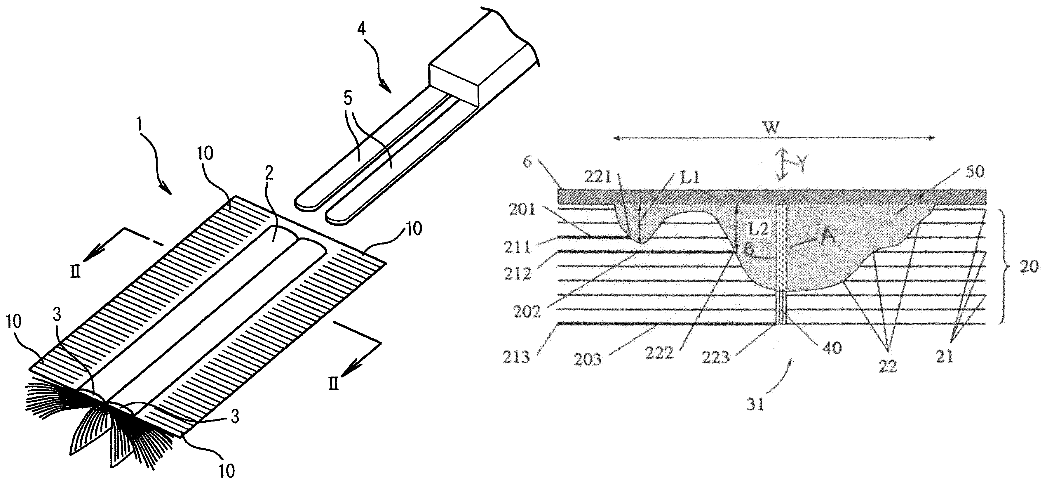
[0041]In the following, embodiments of the present invention will be described specifically with reference to the drawings. The present invention, however, is not restricted to the following embodiments, for example, in terms of the outer configuration of the fiber bundle and the base material sheet, the application configuration and application position of the adhesive, the position where the fibers are bundled with each other, and the presence and the configuration of the handle. FIG. 1 is a perspective view of a cleaning device according to the present invention.

[0042]In the drawing, reference numeral 1 indicates a cleaning device. The cleaning device 1 has a handle mounting portion 2. Support bars 5 of a handle 4 are inserted into insertion holes 3 of the handle mounting portion 2, whereby the cleaning device can be used as a hand mop. The cleaning device 1 of the present invention is formed by integrally bonding a base material sheet 6 to a fiber bundle 7 consisting of a large ...

second embodiment

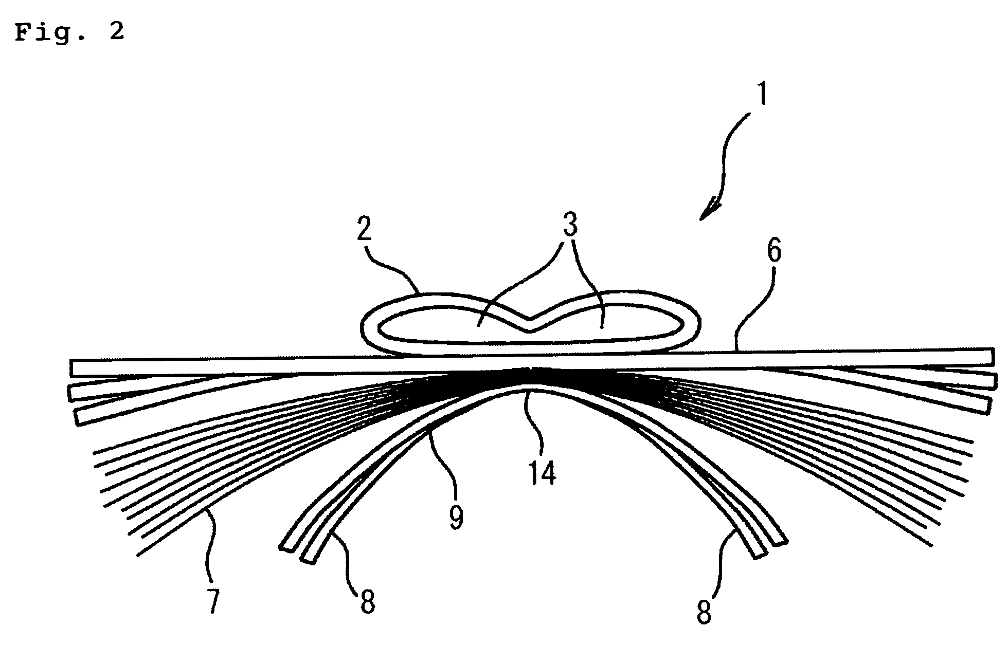
[0055]FIG. 5 is a perspective view of a fiber bundle 7 according to the present invention. In this embodiment, the fiber bundle 7 for wiping off dust is formed by a filament bundling body 31 in which a large number of filaments 30 aligned in the fiber direction are connected together by a bundling portion 40.

[0056]The fiber direction refers to the longitudinal direction of the filaments 30. In the filament bundling body 31, the fibers are bundled in a state in which their directions are aligned. It should be noted, however, that the filament bundling body 31 does not exclude a construction in which a slight amount of other fibers are mingled so as to extend in a direction crossing the large number of filaments 30 forming the filament bundling body. Further, to achieve the object of the present invention, apart from extending in a straight line to form the filament bundling body 31, the filaments 30 may also be bent entirely or locally. Thus, in the present invention, when it is said...

third embodiment

[0065]FIG. 7 is a perspective view of a cleaning device according to the present invention. In this embodiment, the main cleaning portion 20 is bulged and fluffed into a mop head shape. The filaments 30 are bundled together at the band-like bundling portion 40 to first form the filament bundling body 31. Thereafter, at substantially the central portion with respect to the fiber direction, the filament bundling body 31 and the base material sheet 6 are bonded to each other by means of the adhesive 50 at a band-like bonding portion 51 with a width including the bundling portion 40. The movable portions of the filaments 30 form the main cleaning portion 20. By fluffing the main cleaning portion 20 outside the plane of the base material sheet 6, it is possible to obtain the mop-head-like cleaning device of this embodiment. Since the distal ends 21 can move around in a wide range, the cleaning device of this embodiment is capable of not only capturing dust on a flat surface or a convex s...


PUM

PropertyMeasurementUnit
thicknessaaaaaaaaaa
thicknessaaaaaaaaaa
diameteraaaaaaaaaa

Abstract

A cleaning device superior in dust collecting capacity allows material selection from a wide range of fibers and a base material sheet forming the same and can be produced in a short processing time while preventing thermal deterioration and hardening of the material. A process for producing it is also disclosed. A cleaning device 1 is obtained by providing a large number of filaments 30 aligned in fiber direction with a linear bundling portion 40 connecting the fibers to each other by heat-sealing, forming a filament bundling body 31 previously bundled by the bundling portion 40, and bonding the filament bundling body 31 to a base material sheet 6 by an adhesive. A bristle-like-member-less portion 14 of a brush sheet 9 with a plurality of bristle-like members 8 is integrally bonded to a fiber bundle 7 and the base material sheet 6 by an adhesive.

Description

TECHNICAL FIELD[0001]The present invention relates to a cleaning device for wiping off dirt such as dust and a process for producing the same and, more specifically, to a cleaning device having a sheet-like base material to which fibers are bonded and a process for producing the same.BACKGROUND ART[0002]To remove dust adhering to a piece of furniture such as a chest of drawers, an electric appliance such as a personal computer or a light, a wall in a building, a threshold, a lintel, etc., various cleaning devices have conventionally been used. A typical example of such cleaning devices is a duster. Generally speaking, however, a duster, which removes dust by scattering it away from the object of cleaning, has no function by which it wipes off dust. In order to solve this problem, there has been proposed a cleaning device composed of a sheet of non-woven fabric or the like and a fiber bundle, and is currently in use.[0003]For example, Japanese Patent Application Publication No. 2004-...

Claims


Application Information

Patent Timeline
Patent Type & Authority Patents(United States)
IPC IPC(8): A47L13/12A47L13/38A47L13/20
CPCA47L13/16A47L13/20A47L13/38
Inventor YAMADA, KIKUO
Owner YAMADA KIKUO
Why Eureka
Try Eureka