Surface cleaning apparatus

a surface cleaning and cyclone technology, applied in cleaning machines, sports equipment, applications, etc., can solve the problems of decreasing maneuverability and increasing the overall size of the vacuum cleaner, and achieve the effects of reducing the height of the surface cleaning apparatus, increasing the length of the cyclone, and compactness

Active Publication Date: 2012-04-03
OMACHRON INTPROP
View PDF40 Cites 217 Cited by
  • Summary
  • Abstract
  • Description
  • Claims
  • Application Information

AI Technical Summary

Benefits of technology

[0005]The use of adjacent housings to contain part or all of the air cleaning members of a surface cleaning apparatus and the suction motor permits the surface cleaning apparatus to be more compact. For example, upright vacuum cleaners typically have the air-cleaning members and suction motor positioned one above the other. Therefore, the height, or the linear length, of these components is relatively large. The height of the surface cleaning apparatus may be reduced by having units positioned side-by-side as opposed to stacked or linearly extending as is known in the art. Alternately, or in addition, the length of a cyclone may be increased without increasing the overall height or linear extent of a surface cleaning apparatus.
[0006]Accordingly, the overall height of the surface cleaning apparatus may be reduced by effectively increasing the width of the surface cleaning apparatus. For example, if the two housings are each cylindrical, then the width of the surface cleaning apparatus (from one side of the first housing to the other side of the second housing) equal to the sum of the diameter of each of the two housings.
[0007]Further, by providing housings that are generally parallel, the centre of gravity of the housings is positioned more centrally, thereby increasing the maneuverability of the surface cleaning apparatus, particularly if it is designed to be used while being carried (e.g., strap carriable).
[0012]The second housing may contain a pre-motor and / or a post-motor filter. A screen or the like may be associated with the air outlet from the cyclone to prevent elongate material, such as hair, from passing downstream from the cyclone towards the motor.
[0014]In a particularly preferred embodiment of this aspect, the bottom of the first housing may be pivotally mounted for opening. Accordingly, when a user is carrying a strap carriable vacuum cleaner on the user's shoulder, the bottom of the first housing may be opened while the user is standing beside a garbage receptacle (e.g. a garbage bin). Accordingly, the dirt may be emptied directly from the cyclone housing into the garbage bin. An advantage of this design with a strap carriable vacuum cleaner is that the user may have both hands available for manipulating the vacuum cleaner without having to support any weight of the vacuum cleaner in the user's hands since the weight of the vacuum cleaner will be borne by the shoulder of the user.
[0022]Alternately, or in addition to any embodiment or aspect, the electrical cord is removably mounted to the vacuum cleaner. Alternately, or in addition, the vacuum cleaner may include one or more batteries such that the vacuum cleaner may be operated on household AC current and also on DC power from the batteries (e.g., if the cord is removed or wound on a reel to increase maneuverability).

Problems solved by technology

Increasing the size of the dirt collection receptacle may result in the overall size of the vacuum cleaner being increased to such an extent that the maneuverability of the vacuum cleaner decreases.

Method used


Image

  • Surface cleaning apparatus
  • Surface cleaning apparatus
  • Surface cleaning apparatus

Examples


Embodiment Construction

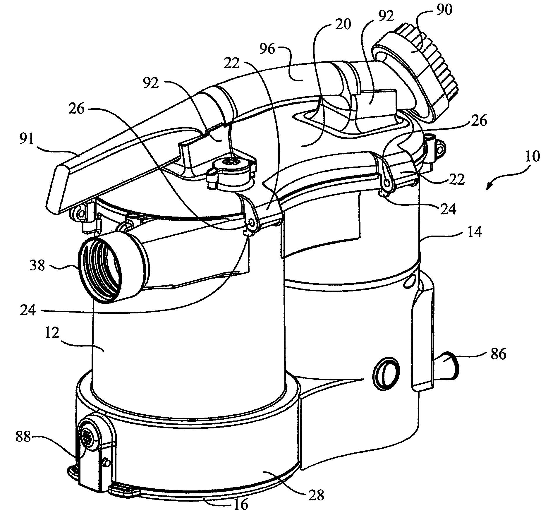
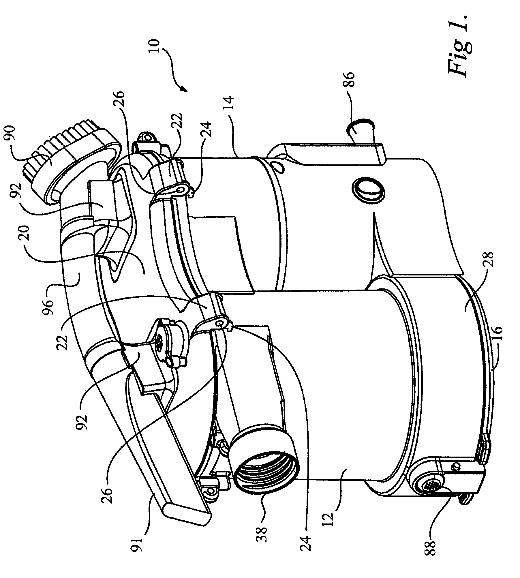
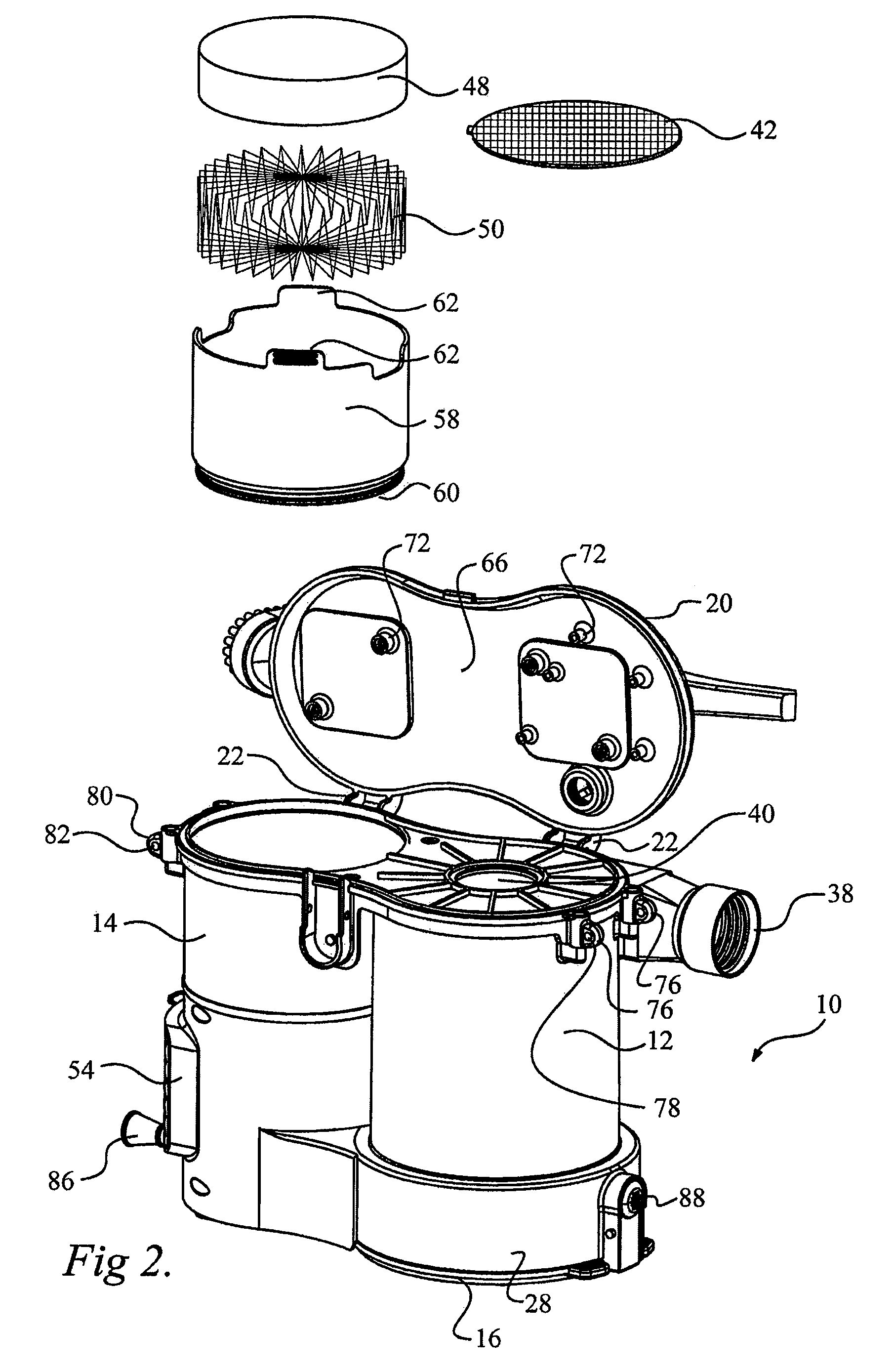
[0151]In accordance with one aspect of this invention, vacuum cleaner 10 comprises a plurality of housings that are adjacent each other. The vacuum cleaner may be a portable vacuum cleaner, e.g., strap carriable as exemplified in FIGS. 1-8 or carriable by a handle as exemplified in FIGS. 15-18 and 24-25, for example a hand vacuum or a wet / dry vacuum cleaner as exemplified in FIGS. 9-14 and 19-22. Preferably, the vacuum cleaner is portable (e.g., hand or strap carriable).

[0152]The Figures exemplify how each of the different aspects disclosed herein may be utilized in a single vacuum cleaner. However, it will be appreciated that each aspect may be used without any of the other aspects. It will be appreciated the vacuum cleaner may be altered to utilize a waist strap in lieu of, or in addition to a shoulder strap and / or a handle.

[0153]For the purpose of this description, a shoulder strap vacuum cleaner as exemplified in FIG. 1 is initially described. As shown therein two housings are u...


PUM


Abstract

A vacuum cleaner comprises adjacent housings, which contain the filtration and suction fan motor assembly of the vacuum cleaner.

Description

FIELD OF THE INVENTION[0001]This application relates to surface cleaning apparatus that have adjacent housings. Preferably, one of the housings contains a cyclonic cleaning stage and a second housing has a suction motor. This application also relates to surface cleaning apparatus that may be carried by a strap (i.e., strap carriable), such as a shoulder strap or a waist strap and, preferably, strap carriable vacuum cleaners, which utilize a cyclone.BACKGROUND OF THE INVENTION[0002]Cyclonic vacuum cleaners have been developed that utilize one or more cyclonic cleaning stages. Each cyclonic cleaning stage may have its own dirt collection chamber. Cyclonic vacuum cleaner that have a cyclonic cleaning stage comprising a plurality of cyclones in parallel are also known. Such cleaning stages may have a dirt collection chamber for each cyclone, or a single common dirt collection chamber for all of the cyclones in the stage. In all such cases, the frequency with which the vacuum cleaner mus...

Claims


Application Information

Patent Timeline
Patent Type & Authority Patents(United States)
IPC IPC(8): A47L9/10
CPCA47L5/24A47L5/36A47L7/0019A47L7/0038A47L7/0042A47L9/0027A47L9/009A47L9/1616A47L9/22
Inventor CONRAD, WAYNE ERNEST
Owner OMACHRON INTPROP
Why Eureka
Try Eureka