Precision crankshaft rotating apparatus and method of crankshaft rotation

Active Publication Date: 2012-04-03
HONDA MOTOR CO LTD
View PDF10 Cites 3 Cited by
  • Summary
  • Abstract
  • Description
  • Claims
  • Application Information

AI Technical Summary

Benefits of technology

[0011]Preferably, a controller is provided for managing operation of the apparatus. The controller is preferably, but not necessarily, microprocessor-based. The controller may be an integral part of the apparatus, or may be located remotely from the remainder of the apparatus while remaining in communication therewith. The controller allows the apparatus to precisely rotate a shaft or crankshaft of interest to one or more desired angular positions.

Problems solved by technology

Obviously, manual rotation of an engine crankshaft is undesirable at least for ergonomic reasons, among others.
Clearly, the positioning accuracy of such a technique is limited.
The above problems are further complicated by the fact that modern internal combustion engines are being increasingly manufactured to tighter tolerances.
As such, manual rotation of an engine crankshaft is also becoming more difficult.

Method used


Image

  • Precision crankshaft rotating apparatus and method of crankshaft rotation
  • Precision crankshaft rotating apparatus and method of crankshaft rotation
  • Precision crankshaft rotating apparatus and method of crankshaft rotation

Examples


Embodiment Construction

)

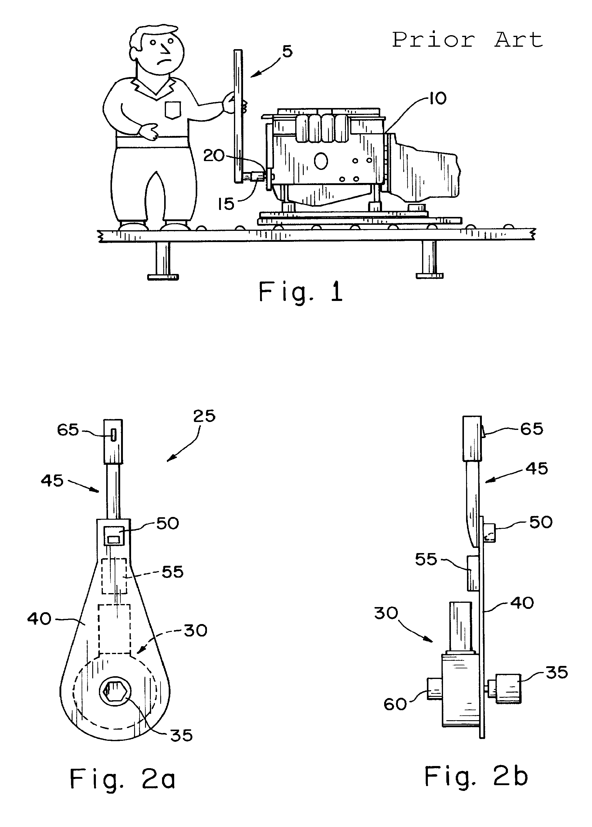
[0021]As described previously and as illustrated in FIG. 1, the manual rotation of an internal combustion engine crankshaft is typically currently accomplished by one or more operators using a long-handled wrench or similar tool 5. FIG. 1 depicts such a process in regard to an internal combustion engine 10 that is still in a state of assembly. As can be seen, the tool 5 includes a socket 15 or some other implement that is adapted to engage an exposed portion of the crankshaft 20. Once the socket 15 is engaged with the crankshaft 20, the tool 5 is used to rotate the crankshaft to a desired rotational position. A position gauge or some other suitable indicator is commonly used to assist the operator in the positioning of the crankshaft. For at least the reasons stated above, this can be understood to be an undesirable crankshaft rotation technique.

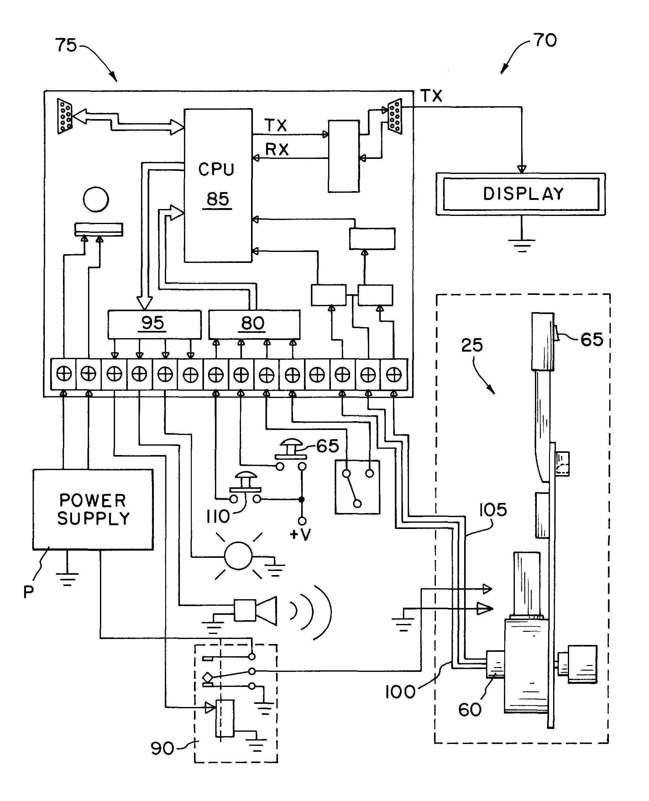
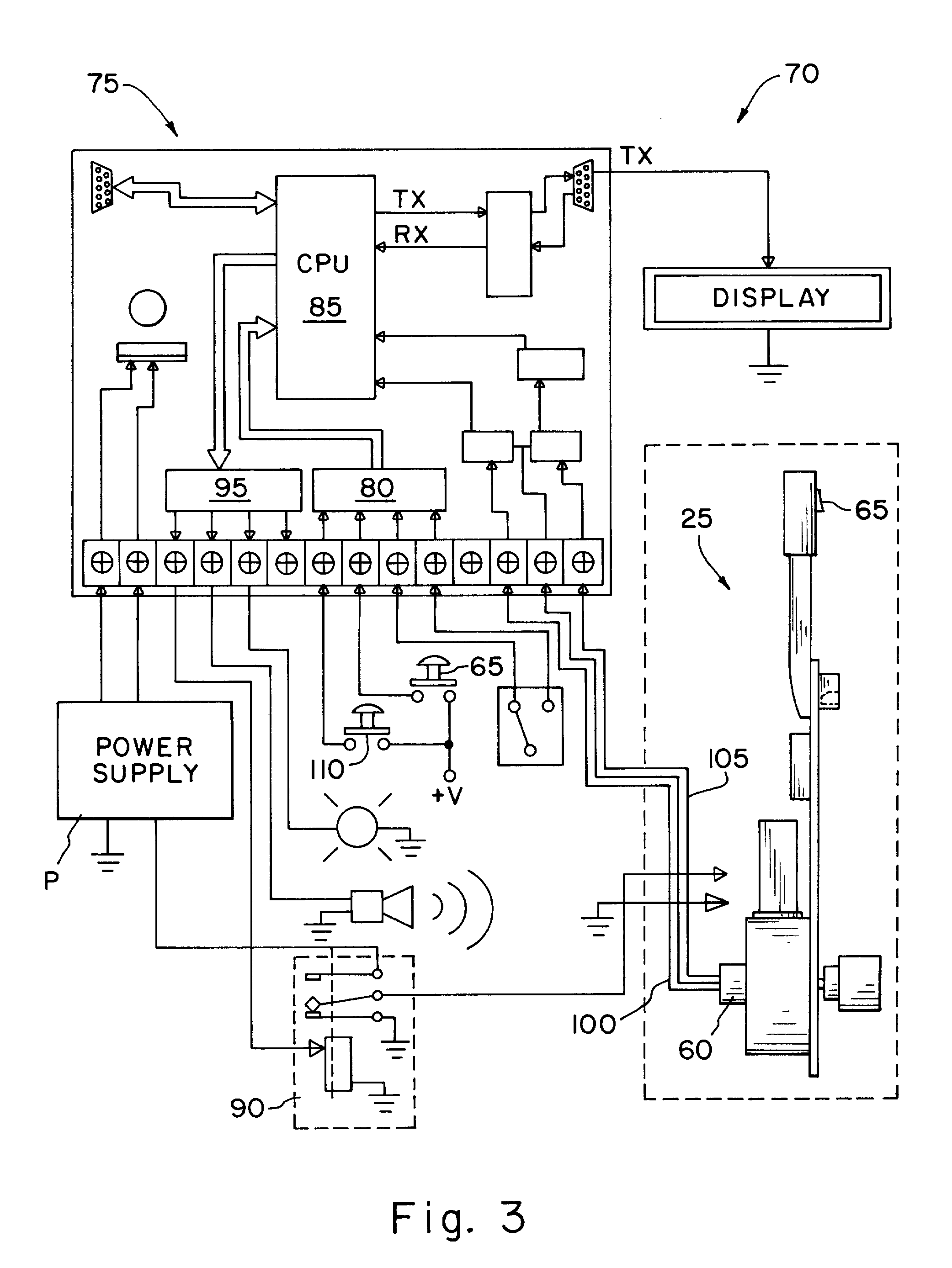
[0022]An apparatus of the present invention eliminates the need to perform crankshaft rotation in the manner illustrated in FIG. 1. One ex...


PUM


Abstract

An apparatus and its method of use for precisely rotating a crankshaft to one or more desired angular positions. The apparatus may include a controller that is programmed to automatically rotate the crankshaft to said one or more positions, or positional control may be allocated to a user of the apparatus. Rotation of the crankshaft is accomplished using a motor or motor / gearbox assembly coupled to a drive element that is adapted to engage an exposed portion of a crankshaft of interest. The angular position of the motor or motor / gearbox assembly and / or the drive element, is monitored, such that the angular position of the crankshaft shaft of interest is known and may be controlled.

Description

BACKGROUND[0001]The present invention is directed to an apparatus for rotating a shaft or crankshaft. More particularly, the present invention is directed to an apparatus for precisely rotating a shaft or crankshaft, such as the crankshaft of an internal combustion engine, to one or more desired angular positions.[0002]It is well known that internal combustion engines require the setting of various valve train components during their assembly. For example, it is typically necessary to set valve tappet clearance to ensure proper engine operation.[0003]Whether in regard to the setting of valve tappet clearance or another valve train adjustment / setting operation, it is generally required to precisely rotate the crankshaft of such an engine in order to properly position the valve train component(s) of interest. Currently, such crankshaft rotation is typically accomplished manually, such as by an operator using a long-handled wrench adapted to engage an exposed portion of the crankshaft....

Claims


Application Information

Patent Timeline
IPC IPC(8): G05G1/04
CPCG05G1/04Y10T74/20582
Inventor RANKIN, BRENT
Owner HONDA MOTOR CO LTD
Why Eureka
Try Eureka