Broadhead

a technology of broadheads and arrows, applied in the field of broadheads, can solve the problems of high frictional force of connections, and achieve the effect of reducing frictional for

Active Publication Date: 2012-04-03
WEAVERS OUTDOOR
View PDF10 Cites 20 Cited by
  • Summary
  • Abstract
  • Description
  • Claims
  • Application Information

AI Technical Summary

Benefits of technology

[0004]The invention is an improved broadhead with expandable front pivot cutting blades where the blades are connected to the broadhead by low-friction rotary connections. The connections reduce frictional forces during outward rotation of the blades and permit locked blade deployment before the blades hit the target.

Problems solved by technology

These connections have high frictional forces when the blades rotate and deploy upon impact.

Method used


Image

  • Broadhead
  • Broadhead
  • Broadhead

Examples


Embodiment Construction

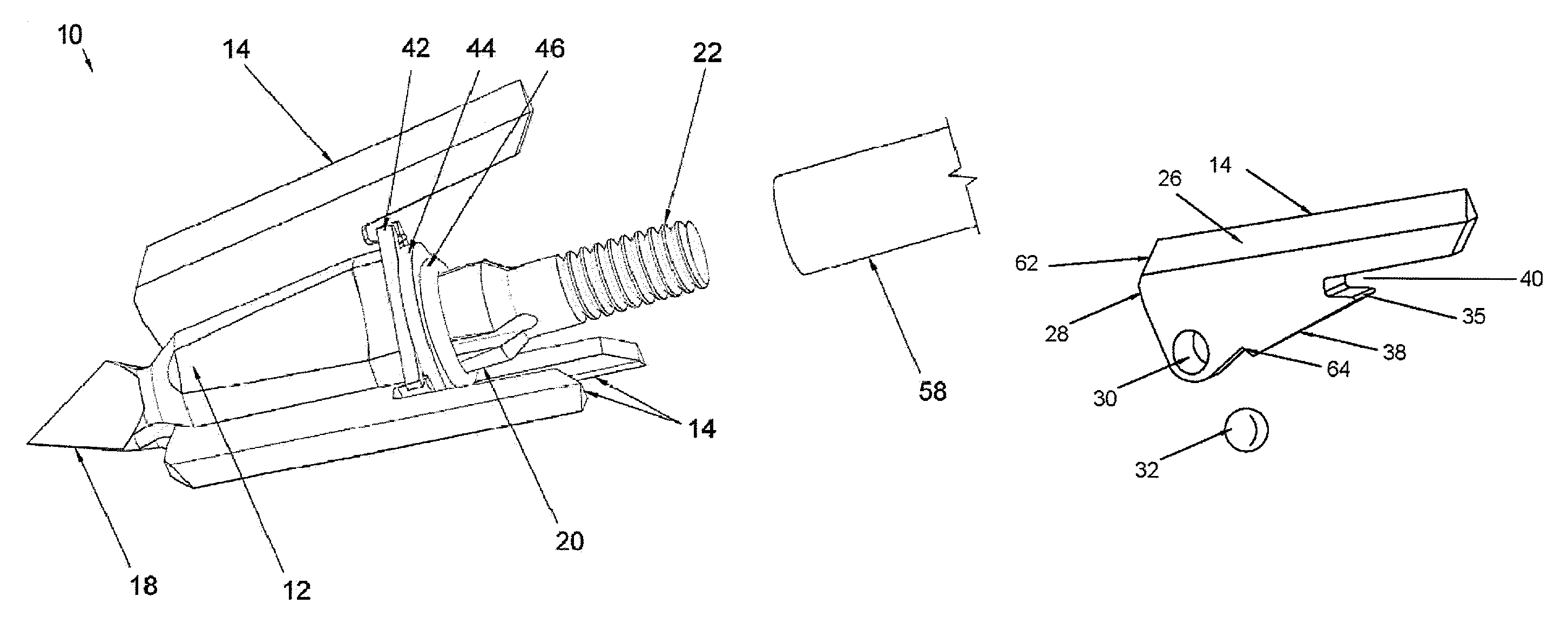
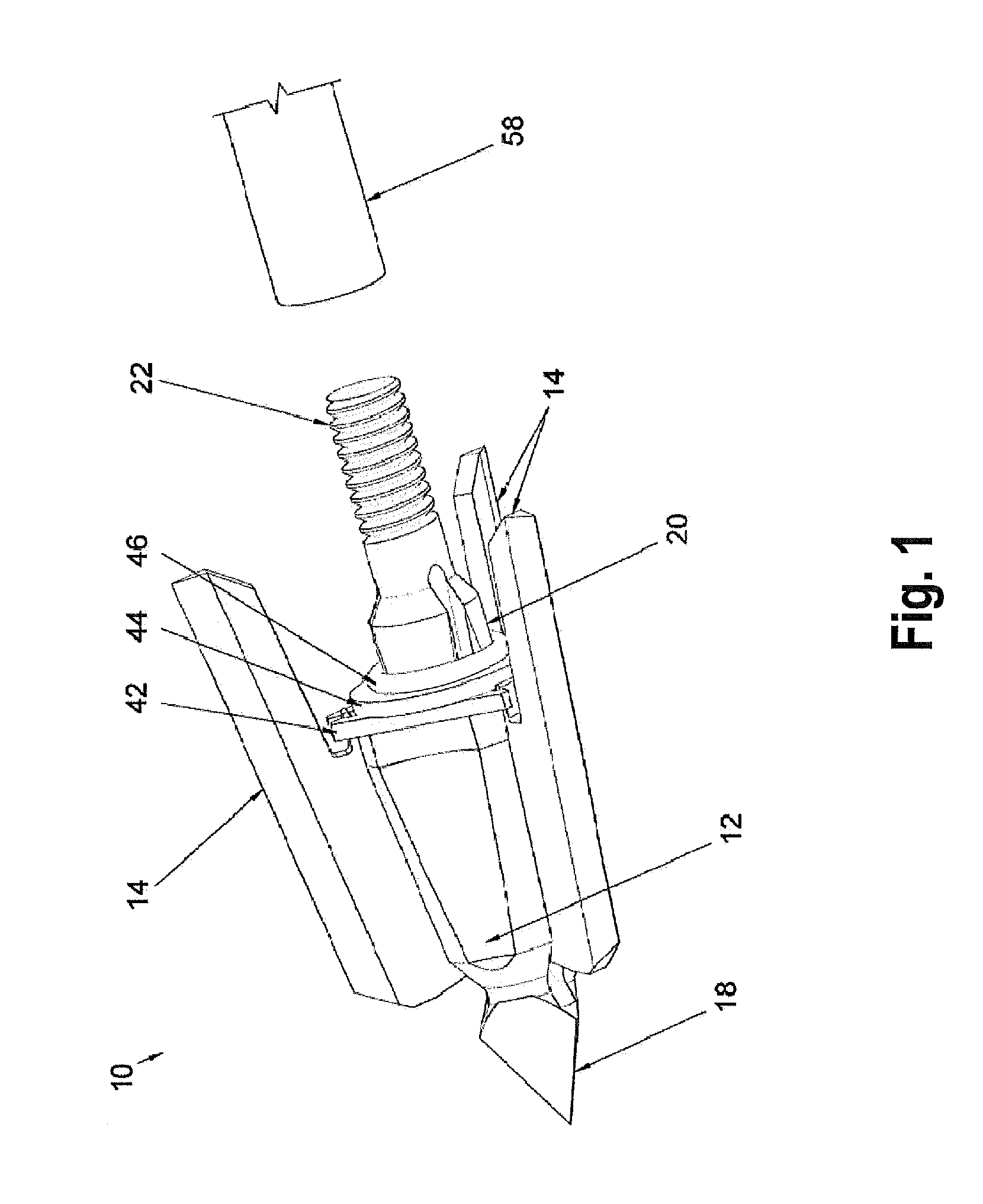
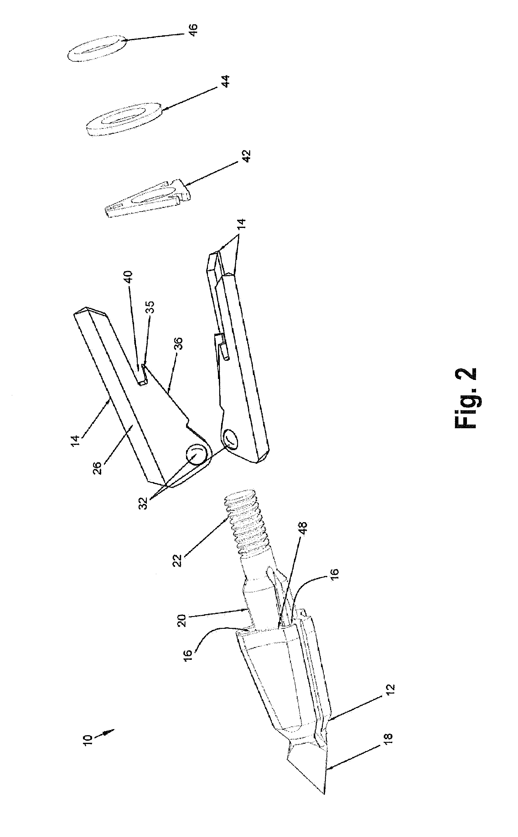
[0021]Broadhead 10 includes a metal ferrule or body 12 mounted on the lead end of an arrow and three cutting blades 14 positioned in three slots 16 in ferrule 12. The slots 16 extend longitudinally and outwardly along ferrule 12 and are spaced apart 120 degrees around the ferrule. Ferrule 12 includes a trocar tip 18 on the lead end of the ferrule, an indexing shaft 20 extending from the trailing end of the ferrule and a reduced-diameter, threaded end 22 extending rearwardly from shaft 20. Ferrule 12 is preferably formed from steel.

[0022]Each blade 14 is preferably formed from uniform-thickness stainless steel. The blades have opposed parallel sides 24, an elongate arm 26 extending from the front to the rear of the blade, and an inwardly extending mounting portion 28 below the forward end of arm 26. Cylindrical hole or passage 30 extends through the front or forward end of portion 28. Mounting member 32, preferably a spherical steel ball, is positioned in hole 30. The ball may be chr...


PUM


Abstract

A broadhead with expandable front pivot cutting blades has the cutting blades connected to the broadhead by low-friction rotary connections. The connections reduce frictional forces during outward rotation of the blades and permit locked blade deployment before the blades hit the target.

Description

BACKGROUND OF THE INVENTION[0001]Conventional broadheads have expandable front pivot cutting blades. The blades are in collapsed positions in the broadhead ferrule during flight and, upon impact, automatically deploy out from the ferrule to locked impact positions. The blades must rapidly rotate outwardly from the collapsed to the impact positions during the short interval between when the ferrule first contacts the target and when the blades contact the target.[0002]Conventional broadheads have rotary connections between the blades and the ferrule. These connections have high frictional forces when the blades rotate and deploy upon impact. The friction slows outward rotation of the blades and can prevent the blades from locked deployment before the blades come into contact with the target. If the blades are not locked in the deployed position, the impact of the broadhead on the target is undesirably reduced.[0003]Thus, there is a need for an improved broadhead having expandable fro...

Claims


Application Information

Patent Timeline
Patent Type & Authority Patents(United States)
IPC IPC(8): F42B6/08
CPCF42B6/08
Inventor WEAVER, ZACHARY T
Owner WEAVERS OUTDOOR
Why Eureka
Try Eureka