Eureka AIR delivers breakthrough ideas for toughest innovation challenges, trusted by R&D personnel around the world.

Gas-insulated high-voltage circuit breaker with a relief duct which is controlled by an overflow valve

a high-voltage circuit breaker and relief duct technology, which is applied in the direction of air-break switches, high-tension/heavy-dress switches, electrical equipment, etc., can solve the problems of high temperature, inability to build up a sufficiently high quenching gas pressure in the heating volume for successful arc blowing, and high current. , to achieve the effect of limiting the pressure of quenching gas

Inactive Publication Date: 2012-04-03
ABB RES LTD
View PDF8 Cites 7 Cited by
  • Summary
  • Abstract
  • Description
  • Claims
  • Application Information

AI Technical Summary

Benefits of technology

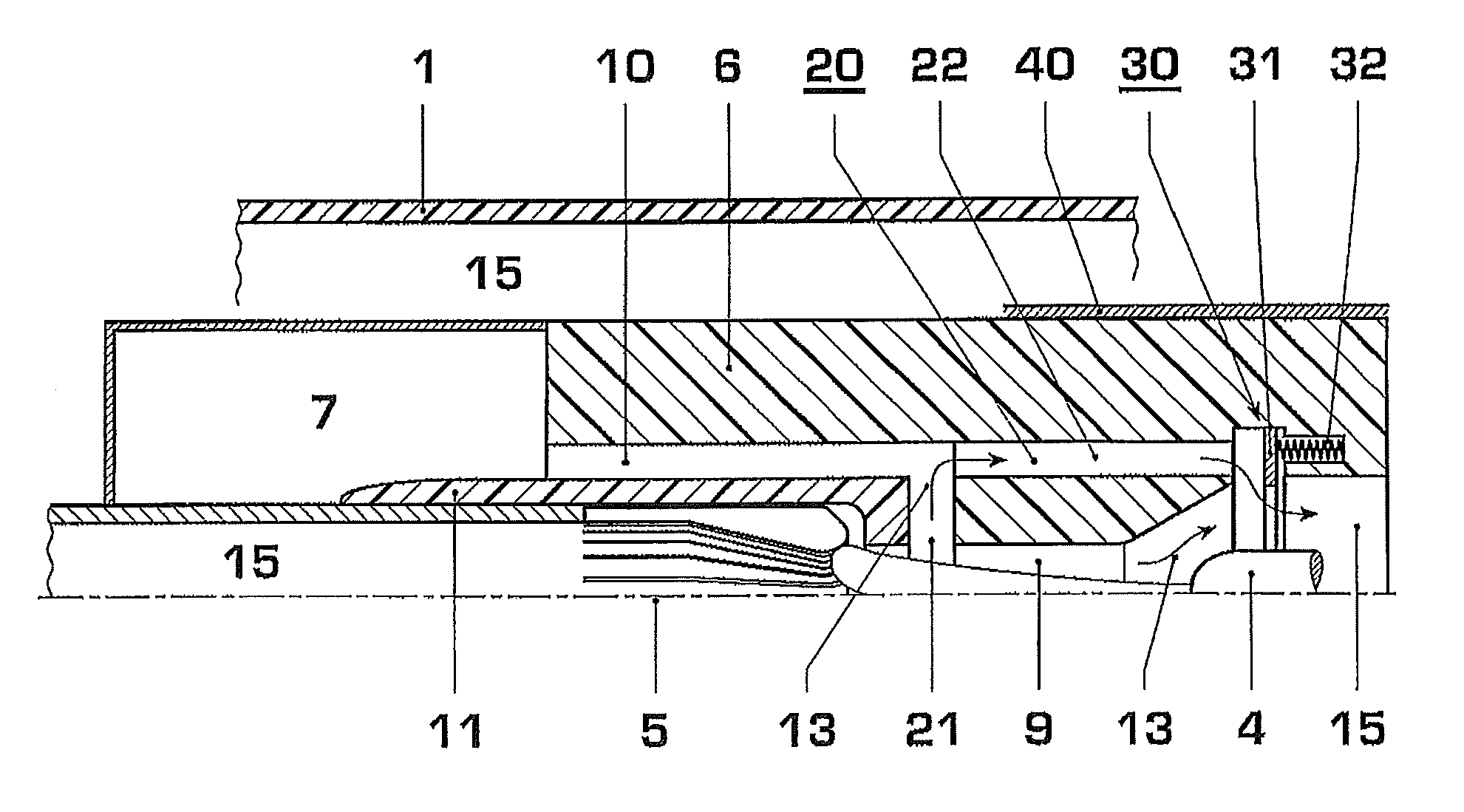
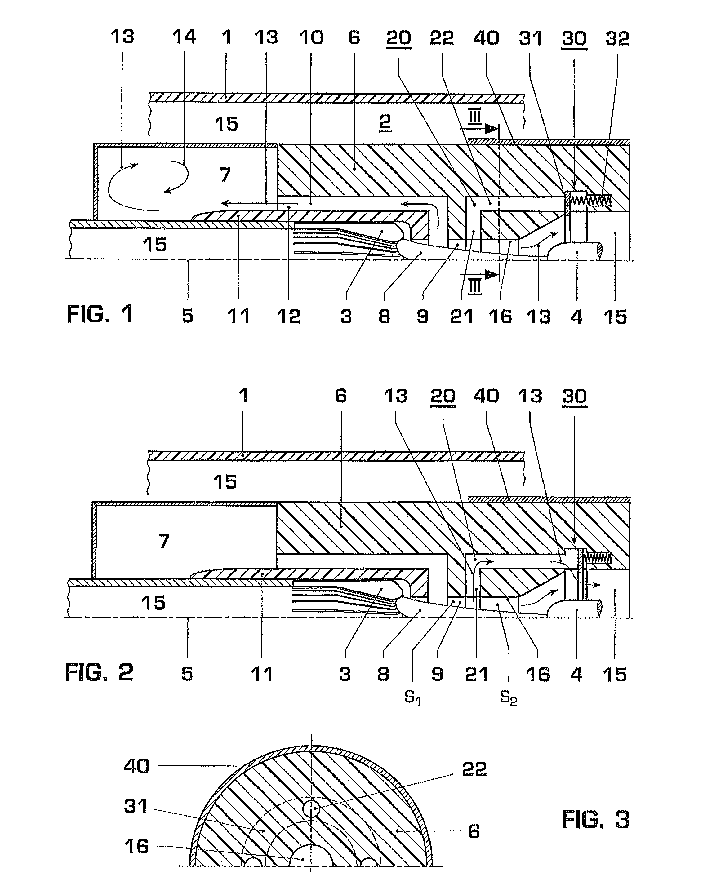
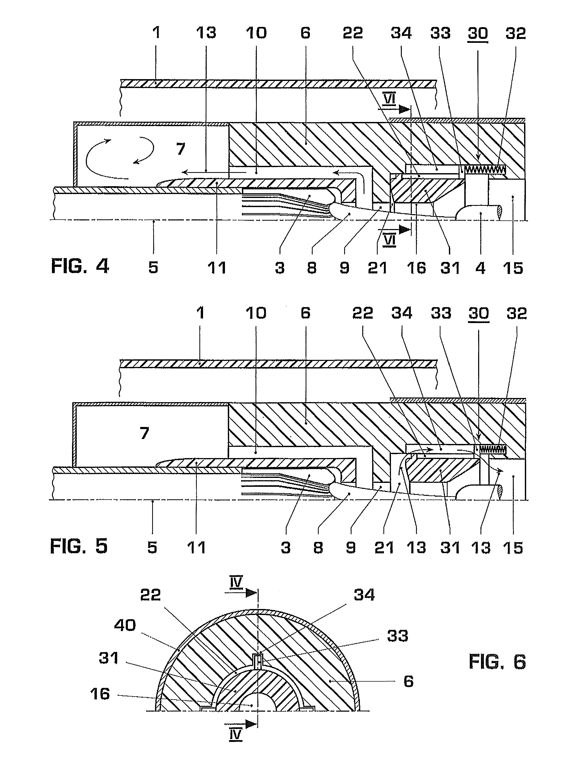
[0015]According to an exemplary embodiment, a relief duct of the breaker is controlled by an overpressure valve and has an outflow section which extends in the radial direction. When switching high currents, therefore, hot arcing gas can be guided radially out of the arc zone or the heating volume once the overpressure valve has responded. Firstly, the insulating nozzle and the heating volume are thus protected from excessive thermal and mechanical loading by virtue of the hot arcing gas. Secondly, however, a quenching gas of good quality is also therefore achieved in the heating volume. This good quenching gas quality is ensured by virtue of the fact that, by limiting the pressure of the arcing gas in the arc zone, excessively hot and excessively highly compressed arcing gas is kept away from the heating volume. If the limiting of the gas pressure first takes place in the heating volume, the hot arcing gas which enters axially into the heating volume is removed radially from the heating volume. A circulation of the quenching gas in the heating volume which is brought about by the hot arcing gas which is flowing in axially, is thus largely suppressed and, as a result, the temperature of the quenching gas provided in the heating volume is kept low. Furthermore, the length of the insulating nozzle in the axial direction can also be kept small since the maximum pressure of the arcing gas in the arc zone is now limited.
[0017]In an exemplary embodiment which is particularly simple to implement, the outflow section is formed as part of the heating channel. In this embodiment and in the embodiment described above with the outflow section formed into the constriction of the insulating nozzle, at least one axially extended section of the relief duct advantageously adjoins the outflow section, and an annular valve body of the overpressure valve is mounted moveably in the axially extended duct section. The arcing gas which is removed from the arc zone after the response of the overpressure valve then passes into the expansion space at a dielectrically uncritical point.

Problems solved by technology

In general, a heating flow triggered by the switching arc in the arc zone and the size of the heating volume are matched in optimum fashion to low-level and mid-level currents, since, when matching two high-level currents, the heating flow would otherwise be much too low for low currents and it would not be possible for a sufficiently high quenching gas pressure for successful arc blowing to be built up in the heating volume.
When switching high currents, arcing gas with a high pressure and a high temperature can therefore form in the arc zone, whereby the arcing gas subjecting both the insulating nozzle and the heating volume to severe mechanical and thermal loads and at the same time has unfavorable quenching gas properties as a result of the high temperature.
As a result, the gas pressure in the control volume drops severely, and a wall which separates the two volumes from one another is moved, which causes a quenching opening to be released and the channel to be sealed.

Method used


Image

  • Gas-insulated high-voltage circuit breaker with a relief duct which is controlled by an overflow valve
  • Gas-insulated high-voltage circuit breaker with a relief duct which is controlled by an overflow valve
  • Gas-insulated high-voltage circuit breaker with a relief duct which is controlled by an overflow valve

Examples


Embodiment Construction

[0014]Exemplary embodiments of the present disclosure provide a high-voltage circuit breaker in which, when switching high currents, the pressure of the arcing gases in the arc zone is limited and, at the same time, the quality of the quenching gas stored in the heating volume is improved.

[0015]According to an exemplary embodiment, a relief duct of the breaker is controlled by an overpressure valve and has an outflow section which extends in the radial direction. When switching high currents, therefore, hot arcing gas can be guided radially out of the arc zone or the heating volume once the overpressure valve has responded. Firstly, the insulating nozzle and the heating volume are thus protected from excessive thermal and mechanical loading by virtue of the hot arcing gas. Secondly, however, a quenching gas of good quality is also therefore achieved in the heating volume. This good quenching gas quality is ensured by virtue of the fact that, by limiting the pressure of the arcing ga...


PUM


Abstract

A high-voltage circuit breaker includes two arcing contacts, which are capable of moving relative to one another along an axis, an insulating nozzle, a heating volume for accommodating quenching gas, a heating channel, and an overpressure valve. The pressure of the quenching gas is based on the energy of a switching arc, which is formed when the breaker opens and generates arcing gas, and the heating channel opens out, with axial alignment, into the heating volume. The heating channel connects an arc zone, and the overpressure valve limits the pressure of the quenching gas by opening a relief duct, which opens out into an expansion space. In high-current switching, the pressure of the arcing gases in the arc zone is limited, and the quality of the quenching gas stored in the heating volume is improved, due to the relief duct having an outflow section extending in the radial direction.

Description

RELATED APPLICATIONS[0001]This application claims priority as a continuation application under 35 U.S.C. §120 to PCT / EP2007 / 061005 filed as an International Application on Oct. 16, 2007 designating the U.S., the entire content of which is hereby incorporated by reference in its entirety.FIELD[0002]The present disclosure relates to a gas-insulated high-voltage circuit breaker.BACKGROUND INFORMATION[0003]Gas-insulating high-voltage breakers are used in an electrical network carrying high voltages for connecting and disconnecting current having an intensity which ranges from very low inductive and capacitive current through normal load current up to medium and high short-circuit current. It is generally possible with such breakers to interrupt short-circuit currents in the region of 50 kA or above in a voltage range of up to several hundred kV.[0004]A gas-insulated high-voltage circuit breaker of the type mentioned above contains two arcing contacts, which are capable of moving relativ...

Claims


Application Information

Patent Timeline
Patent Type & Authority Patents(United States)
IPC IPC(8): H01H33/88
CPCH01H33/74H01H33/98H01H2033/908
Inventor SEEGER, MARTINNIEMEYER, LUTZIORDANIDIS, ARTHOUROSFRANCK, CHRISTIAN
Owner ABB RES LTD
Why Eureka
Eureka Blog
Learn More