Method for planning a cellular mobile telecommunications network

a cellular mobile and telecommunications network technology, applied in the field of telecommunications, can solve the problems of weak optimization, affecting the efficiency of the whole planning method, and weak limitation of the known planning method

Active Publication Date: 2012-04-03
TELECOM ITALIA SPA
View PDF13 Cites 6 Cited by
  • Summary
  • Abstract
  • Description
  • Claims
  • Application Information

AI Technical Summary

Benefits of technology

[0030]In view of the outlined state of the art and related problems, drawbacks and limitations, the Applicant has tackled the general problem of improving the known planning methods of cellular mobile telecommunications networks.
[0031]In particular, the Applicant has tackled the problem of how to properly carry on the phases for the uplink analysis in the planning process of a CDMA network.

Problems solved by technology

The Applicant has observed that the methods known in the art for planning a UMTS network, particularly concerning the uplink power control phase, suffer from limitations that impact the efficiency of the whole planning method, and the networks built following such methods are as a consequence not optimized.
The Applicant has observed that a strong limitation of the known planning methods, like that described in the cited document, is the dependence of the results, produced by the uplink power control phase, on the assumptions made in the preliminary, admission control phase.
As a consequence, the calculation areas thus determined, on which the following uplink power control phase is based, may be not sufficiently close to the real interferential conditions, which are not known until after the uplink power control phase, and the global service areas that are calculated may be unrealistic and cause network malfunctioning.

Method used


Image

  • Method for planning a cellular mobile telecommunications network
  • Method for planning a cellular mobile telecommunications network
  • Method for planning a cellular mobile telecommunications network

Examples


Embodiment Construction

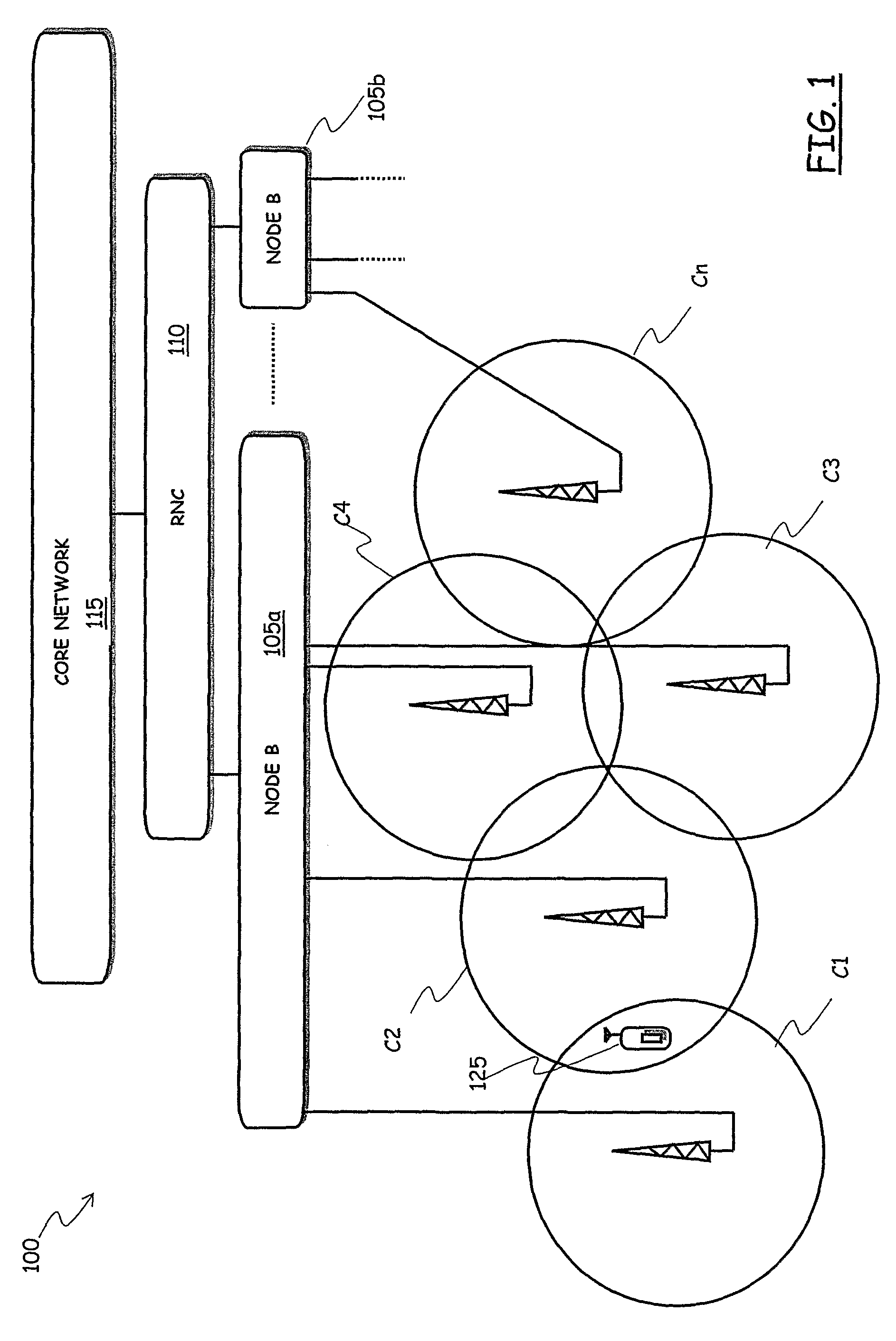
[0062]Referring to the drawings, in FIG. 1 there is schematically depicted a portion of a CDMA network, particularly a UMTS network under planning, the network portion being intended to provide cellular mobile communications capability within a given geographic area.

[0063]The UMTS network portion under consideration, identified globally by reference numeral 100, comprises a plurality of cells C1, C2, C3, C4, . . . , Cn (schematically depicted as circles), each one having a respective area coverage (the area of the circles). The cells C1, C2, C3, C4, . . . , Cn are each one made up of a plurality of pixels, i.e., they are the set of geographic points covered and served by the radio electromagnetic signal irradiated by a respective cell's BRS, schematized in the drawing as an antenna.

[0064]Usually, groups of three to six cells (on average) are managed by a network entity called “Node B”, such as the Node Bs 105a and 105b in the drawing (where, merely by way of example, it is assumed t...


PUM


Abstract

A method for planning a cellular mobile telecommunications network includes at least one network cell and is intended to provide network services to users located in the network cell. The method includes: a) initializing, for the at least one network cell, a service area and a transmission power for each user equipment; b) estimating a total power received by the at least one network cell from user equipment located in the service area and using the at least one network service; c) based on the estimated total received power, varying the transmission powers required to user equipment located in the service area in order to reach a target quality of service constraint for the at least one network service; d) iterating the steps b) and c) until a stability condition is reached wherein the transmission power variation for at least a predetermined fraction of the user equipment is lower than a predetermined threshold; e) calculating a total received power corresponding to the transmission powers at the end of step d); f) calculating an uplink load factor corresponding to the total received power calculated in step e); g) ascertaining whether the calculated uplink load factor is lower than a maximum uplink load factor, and, in the negative case: h) restricting said service area; and i) repeating the steps from b) to g).

Description

CROSS REFERENCE TO RELATED APPLICATION[0001]This application is a national phase application based on PCT / EP2005 / 010591, filed Sep. 30, 2005, the content of which is incorporated herein by reference.FIELD OF THE INVENTION[0002]The present invention generally relates to the field of telecommunications, particularly to mobile telecommunications networks, allowing communications between mobile users. More specifically, the invention relates to cellular mobile telecommunications networks, particularly to radio telecommunications networks, and even more particularly to those networks that adopt a Code Division Multiple Access (CDMA) or Wideband CDMA (WCDMA) access scheme, such as cellular networks of the third generation, like those complying with the Universal Mobile Telecommunications System (UMTS).BACKGROUND OF THE INVENTION[0003]Mobile telecommunications networks are usually arranged according to a cellular structure comprising a plurality of cells, each cell being defined as the set...

Claims


Application Information

Patent Timeline
Patent Type & Authority Patents(United States)
IPC IPC(8): H04B7/185H04J3/12H04W16/00H04B7/26H04W16/02H04W16/08H04W16/18
CPCH04W16/02H04W16/18H04W16/08H04W52/04
Inventor PANICO, MASSIMILIANOFRANCALANCI, INDRO
Owner TELECOM ITALIA SPA
Why Eureka
Try Eureka