
System and method for monitoring particulate filter performance

a technology of particulate filter and monitoring system, which is applied in the direction of liquid degasification, auxillary pretreatment, separation process, etc., can solve the problems of increasing the emission of particulate matter well above the regulated limit, affecting and reducing the efficiency of the filter. , to achieve the effect of reducing the filter trapping efficiency and efficiently and effectively monitoring the performance of the filter

Active Publication Date: 2012-04-10
FORD GLOBAL TECH LLC
View PDF18 Cites 16 Cited by
  • Summary
  • Abstract
  • Description
  • Claims
  • Application Information

AI Technical Summary

Benefits of technology

The patent text describes a system for monitoring the performance of particulate filters in automotive emissions control systems. The system uses an image charge sensor to detect changes in exhaust flow caused by the filter and measures the rate of change in flow to determine if the filter is becoming less efficient. The system can provide a practical solution for monitoring particulate emissions in automobiles and can be used in conjunction with other diagnostic instruments to detect and remedy any issues with the filter. The technical effect of the patent is to provide a reliable and cost-effective method for monitoring the performance of particulate filters in real-time, which can help to ensure that emissions standards are met and can also help to prevent damage to the filter due to uncontrolled engine operating conditions.

Problems solved by technology

However, over time, such filters can suffer irreversible decreases in trapping efficiencies as the filter develops cracks due to uncontrolled temperature excursion during the filter regeneration process, by means of which the soot accumulated in the filter is burned off under controlled engine operating conditions.
Losses in trapping efficiency may result in increased particulate matter emissions well above the regulated limit.
Furthermore, some of these instruments, such as instruments that utilize optical measurement techniques, may require periodic cleaning.
Therefore, these instruments may be too expensive and difficult to use under normal automobile operating conditions to be a practical solution to monitoring particulate emissions in automobiles.
Furthermore, other methods for detecting a particulate filter failure, such as the differential pressure method in which a pressure differential across the filter is monitored, may not be suitable for detecting a failure of the filter due to interference effects from ash loading in the filter.

Method used


Image

  • System and method for monitoring particulate filter performance
  • System and method for monitoring particulate filter performance
  • System and method for monitoring particulate filter performance

Examples


Embodiment Construction

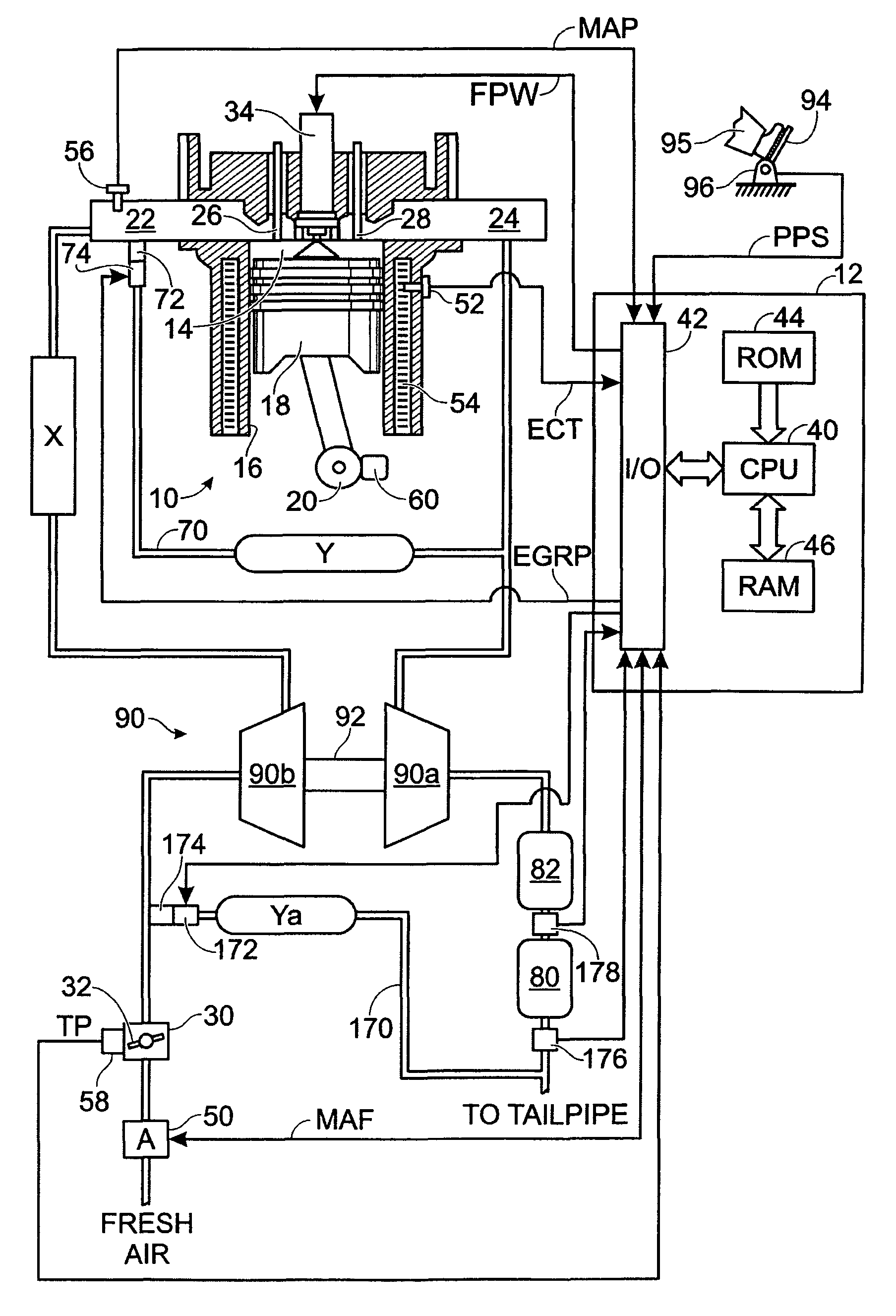
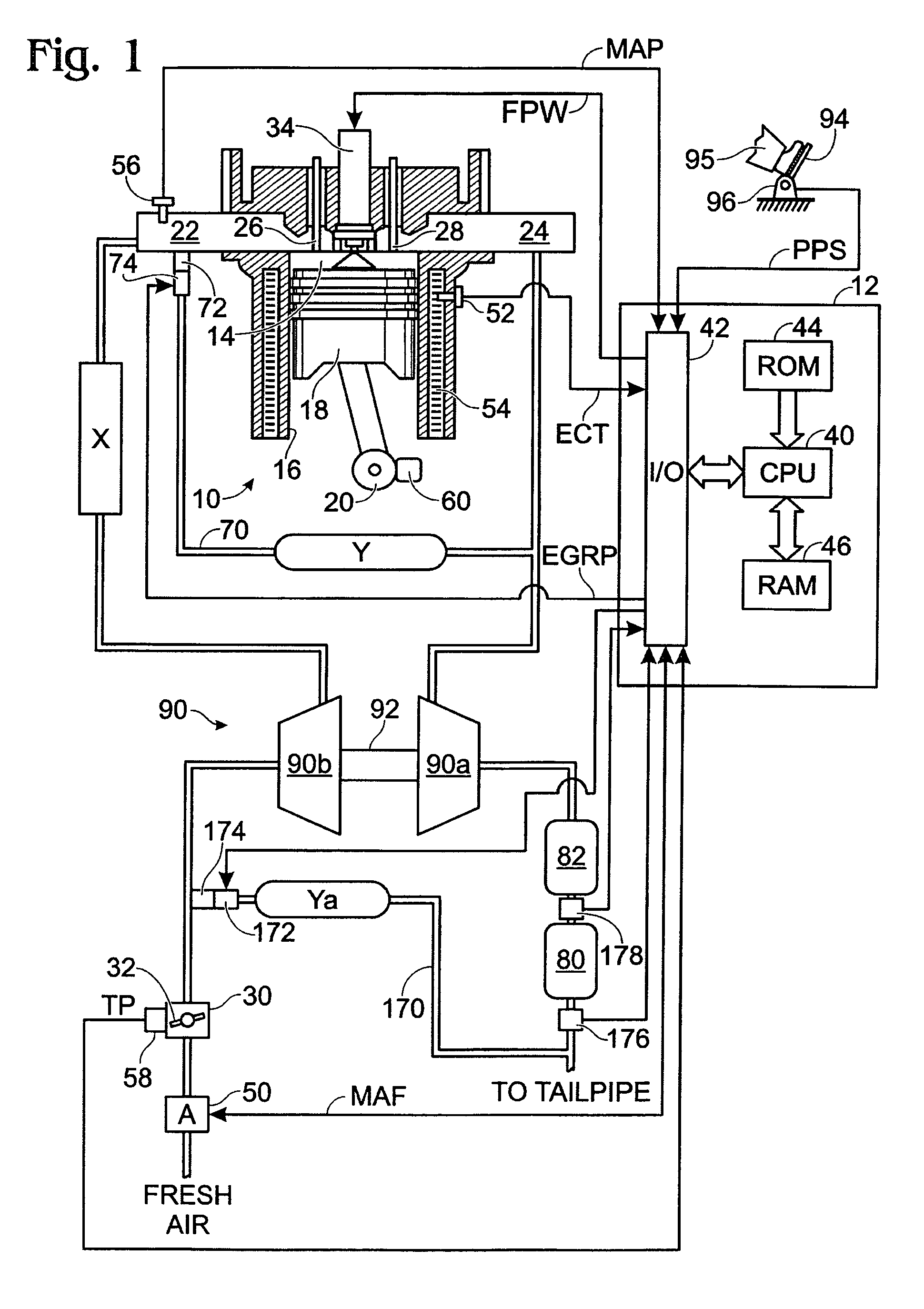
[0014]FIG. 1 shows an exemplary embodiment of a diesel engine system generally at 10. Specifically, internal combustion engine 10 comprises a plurality of cylinders, one cylinder of which is shown in FIG. 1. Engine 10 is controlled by electronic engine controller 12. Engine 10 includes combustion chamber 14 and cylinder walls 16 with piston 18 positioned therein and connected to crankshaft 20. Combustion chamber 14 communicates with an intake manifold 22 and an exhaust manifold 24 via respective intake valve 26 and exhaust valve 28.

[0015]Intake manifold 22 communicates with throttle body 30 via throttle plate 32. In one embodiment, an electronically controlled throttle can be used. In one embodiment, the throttle is electronically controlled to periodically, or continuously, maintain a specified vacuum level in intake manifold 22. Alternatively, throttle body 30 and throttle plate 32 may be omitted.

[0016]Combustion chamber 14 is also shown having fuel injector 34 coupled thereto for...


PUM

PropertyMeasurementUnit
frequencyaaaaaaaaaa
frequencyaaaaaaaaaa
thresholdaaaaaaaaaa

Abstract

In an apparatus having an internal combustion engine, an exhaust system for transporting engine exhaust from the engine is described. In one example, a particulate filter disposed in the exhaust system is assessed for degradation. The approach may be particularly useful for an image charge sensor.

Description

TECHNICAL FIELD[0001]The present application relates to the field of automotive emission control systems and methods.BACKGROUND AND SUMMARY[0002]Particulate matter filters are increasingly used in automotive emissions systems for reducing particulate concentrations in engine exhaust. However, over time, such filters can suffer irreversible decreases in trapping efficiencies as the filter develops cracks due to uncontrolled temperature excursion during the filter regeneration process, by means of which the soot accumulated in the filter is burned off under controlled engine operating conditions. Losses in trapping efficiency may result in increased particulate matter emissions well above the regulated limit.[0003]Increasingly stringent particulate matter emissions standards and proposed government-mandated on-board diagnostic (OBD) requirements for monitoring the trapping efficiency of a particulate filter have stimulated much research into new techniques for monitoring particulate f...

Claims


Application Information

Patent Timeline
Patent Type & Authority Patents(United States)
IPC IPC(8): F01N3/00
CPCF01N11/00F01N2550/04F01N2900/0421F01N2900/0422Y02T10/47Y02T10/40Y10S55/30
Inventor ZANINI-FISHER, MARGHERITAVAN NIEUWSTADT, MICHIEL J.
Owner FORD GLOBAL TECH LLC
Learn More