
Loop lock having offset cylinder axis

a technology of offset cylinder and lock body, which is applied in the field of loop locks, can solve the problems of relative bulky design of the lock body, and achieve the effect of compact construction and simple production

Active Publication Date: 2012-04-10
ABUS AUGUST BREMICKER SOEHNE AG
View PDF35 Cites 15 Cited by
  • Summary
  • Abstract
  • Description
  • Claims
  • Application Information

AI Technical Summary

Benefits of technology

[0005]It is therefore the object of the present invention to provide a lock of the initially named kind which is simple to produce and is compact in construction and in which nevertheless a secure fastening of the first end of the loop can be ensured.
[0007]In contrast to a purely coaxial arrangement of the cylinder core with respect to the lock body or to the cylinder housing known from the prior art, the cylinder housing thus has a larger thickness in the region of the fastening point which is required for a mechanically stressable fastening of the first end of the loop without, however, the cylinder housing having to be widened outwardly in the region of the fastening point or having to be provided with moldings. A slimmer cylinder housing and a correspondingly small constructional shape of the lock body thus result overall without compromises in the security.
[0008]The loop lock in accordance with the invention is also able to be made lighter and less expensively due to the thereby possible cylindrical construction shapes of the lock body or of the cylinder housing, which are easy to manufacture, without additional moldings for the reception of the first end of the loop.
[0012]In a further preferred embodiment, locking elements are arranged in the locking element receivers which engage into a peripheral groove of a bolt received in the bolt receiver and forming the second end of the loop and which can escape back into the escape openings for a release of the bolt in the release position in dependence on a rotary position of the inner sleeve relative to the axial prolongation in a closed position. A very compact closing mechanism is thereby implemented which nevertheless fixes the bolt in the bolt receiver in the closed position.
[0014]The cylinder core preferably has a catch pin at its end face remote from the key receiver, said catch pin being arranged eccentrically to the axis of rotation of the cylinder core and cooperating with a cam gate, in particular with an elongate hole, provided at an end face of the inner sleeve facing the cylinder core for the actuation of the inner sleeve. The combination of catch pin and cam gate implements in a simple manner a transmission of a rotary movement of the cylinder core onto the inner sleeve despite the axial offset of the axes of rotation of the cylinder core and of the inner sleeve.

Problems solved by technology

However, this results in a relatively bulky design of the lock body.

Method used


Image

  • Loop lock having offset cylinder axis
  • Loop lock having offset cylinder axis
  • Loop lock having offset cylinder axis

Examples


Embodiment Construction

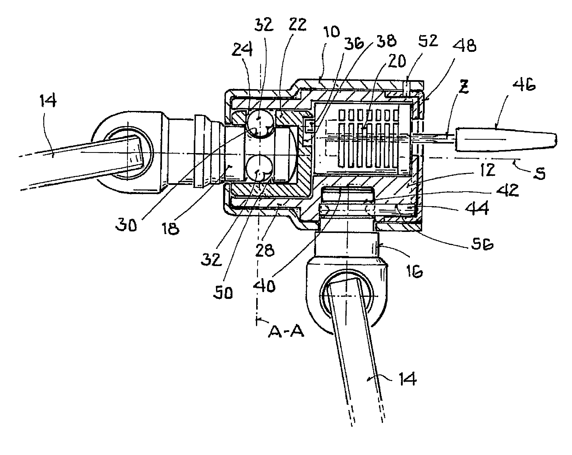
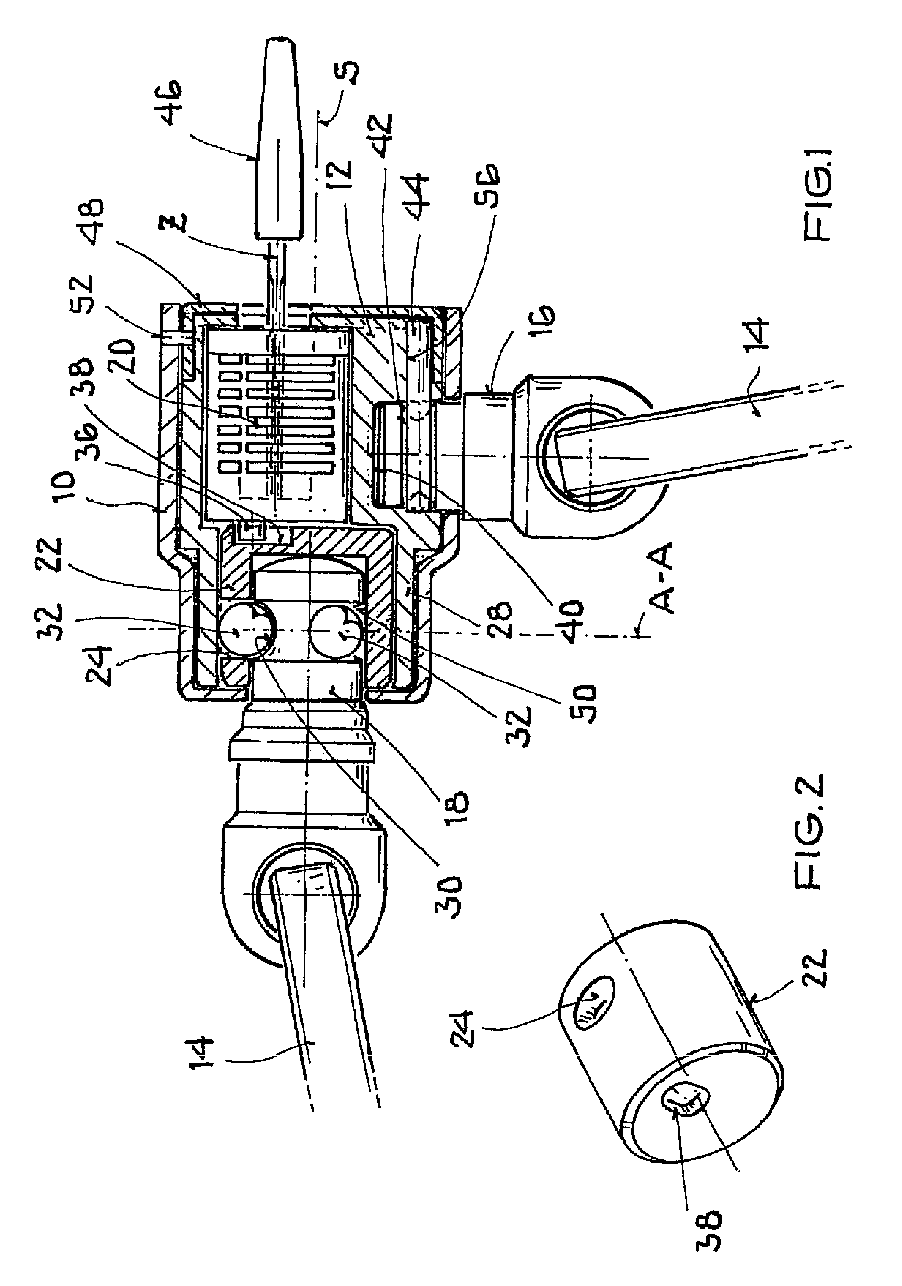
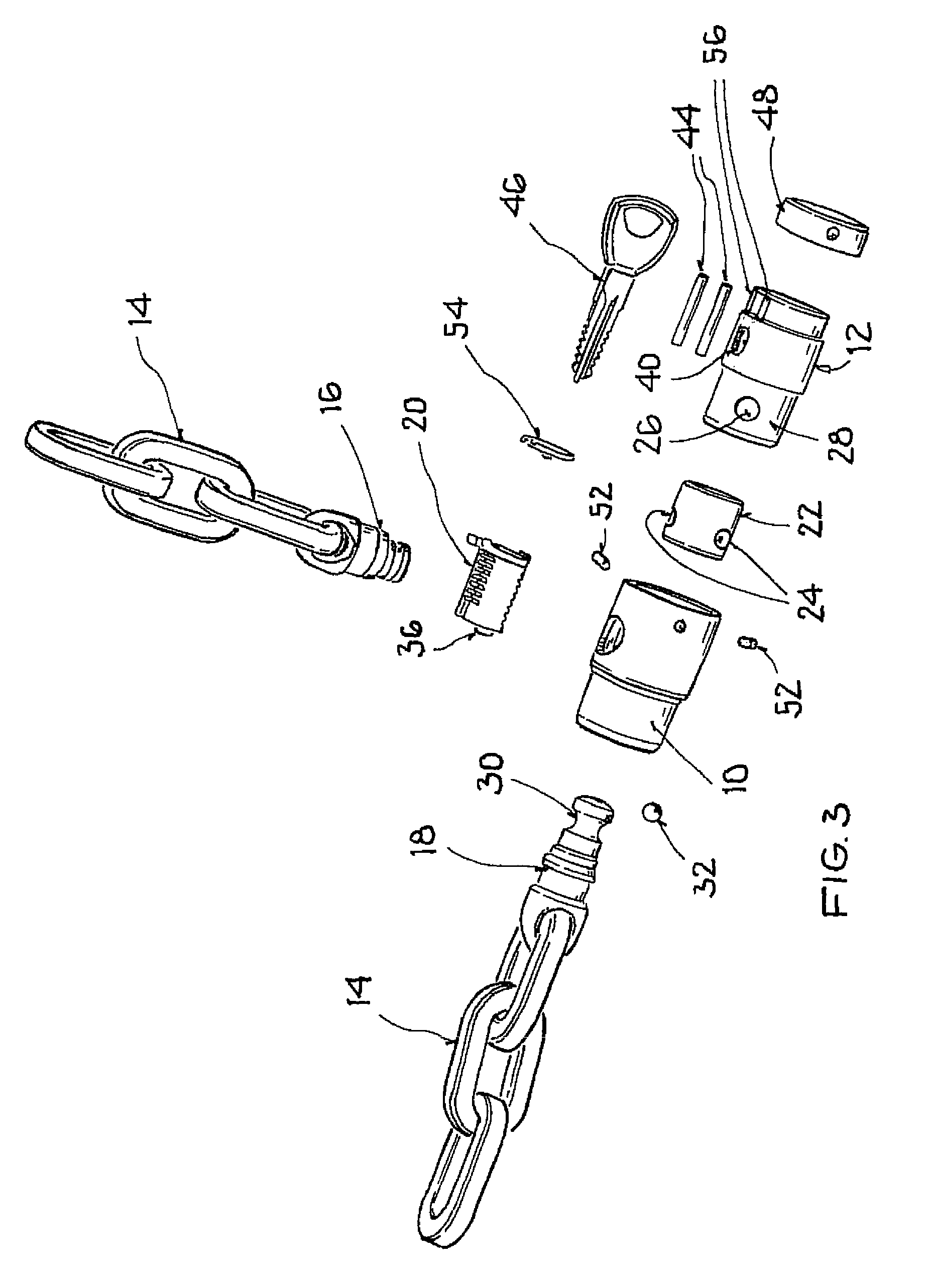
[0023]In accordance with FIGS. 1 to 6, a loop lock in accordance with the invention includes a cylindrical body 10 which surrounds a likewise cylindrical cylinder housing 12 of a lock cylinder. A cylinder core 20 is provided in the cylinder housing 12 and has a plurality of blocking members which are known per se and which can be actuated by means of a key 46. In a closed position of the loop lock in accordance with the invention, a rotation of the cylinder lock 20 is not possible when the key 46 has been removed. The axis of rotation Z of the cylinder core 20 is offset in parallel with respect to the longitudinal axis S of the lock body 10.

[0024]The cylinder housing 12 has different wall thicknesses in the region of the cylinder core 20 due to this offset. In the peripheral region of the largest wall thickness, a connector piece receiver 40 in the form of a radial bore is provided in which a connector piece 16 of a loop 14 is received. In the present embodiment, the loop 14, only s...


PUM


Abstract

The invention relates to a loop lock, in particular to a chain lock or to a wire cable lock, having a lock body which has a longitudinal axis and which surrounds a cylinder housing of a lock cylinder and having a loop, wherein the first end of the loop is permanently fastened to a fastening point of the cylinder housing and is aligned perpendicular to the longitudinal axis of the lock body, wherein a second end of the loop can be releasably fastened to a longitudinal end of the lock body and is aligned coaxially to the longitudinal axis of the lock body; and wherein a cylinder core of the lock cylinder is rotatably journalled about an axis of rotation in the cylinder housing and is characterized in that the axis of rotation of the cylinder core is offset in parallel with respect to the longitudinal axis of the lock body, namely away from the fastening point for the first end of the loop.

Description

CROSS-REFERENCE TO RELATED APPLICATION[0001]This application claims priority of German Patent Application 10 2009 039 156.8 filed Aug. 27, 2009, which is incorporated herein by reference.FIELD OF THE INVENTION[0002]The present invention relates to a loop lock, in particular to a chain lock or to a wire cable lock, having a lock body which has a longitudinal axis and which surrounds a cylinder housing of a lock cylinder and having a loop, wherein a first end of the loop is permanently fastened to a fastening point of the cylinder housing and is aligned perpendicular to the longitudinal axis of the lock body, wherein a second end of the loop is releasably fastened to a longitudinal end of the lock body and is aligned coaxially to the longitudinal axis of the lock body, and wherein a cylinder core of the lock cylinder is rotatably journalled about an axis of rotation in the cylinder housing.BACKGROUND OF THE INVENTION[0003]Such a loop lock is known from DE 44 34 585 A1.[0004]In such a ...

Claims


Application Information

Patent Timeline
Patent Type & Authority Patents(United States)
IPC IPC(8): E05B73/00
CPCE05B67/365E05B67/003Y10T70/40Y10T70/415Y10T70/483Y10T70/5009Y10T70/5872Y10T70/7751
Inventor THOMAS, MANUELNG, HOI JARMNG, LEGAL REPRESENTATIVE, WAI LEUNG
Owner ABUS AUGUST BREMICKER SOEHNE AG
Learn More