Cover for temperature sensor

a temperature sensor and cover technology, applied in the field of refrigeration systems, can solve the problems of inconvenient reapplication, difficult removal, inconsistent reapplication results,

Active Publication Date: 2012-04-10
CARRIER CORP
View PDF12 Cites 5 Cited by
  • Summary
  • Abstract
  • Description
  • Claims
  • Application Information

AI Technical Summary

Benefits of technology

[0005]Briefly, in accordance with one aspect of the invention, a molded foam cover is wrapped around the bulb that is attached to the outlet line, and the cover is secured in place so as to insulate the bulb and protect it from exposure to moisture and air currents.

Problems solved by technology

First, the quality of the resulting insulation is dependent on the ability of the technician applying it, and there is no certainty that the process will be inadequate.
Secondly, in order for the serviceman to have access to the bulb for inspection and / or maintenance purposes, it is necessary to remove each of these layers and then reapply them when the process is completed.
The removal is difficult, especially the Prestite, and the reapplication results are inconsistent, as mentioned hereinabove.
Both are very labor intensive and expensive.
These sensors are subject to the same problems as discussed hereinabove.

Method used


Image

  • Cover for temperature sensor
  • Cover for temperature sensor
  • Cover for temperature sensor

Examples


Embodiment Construction

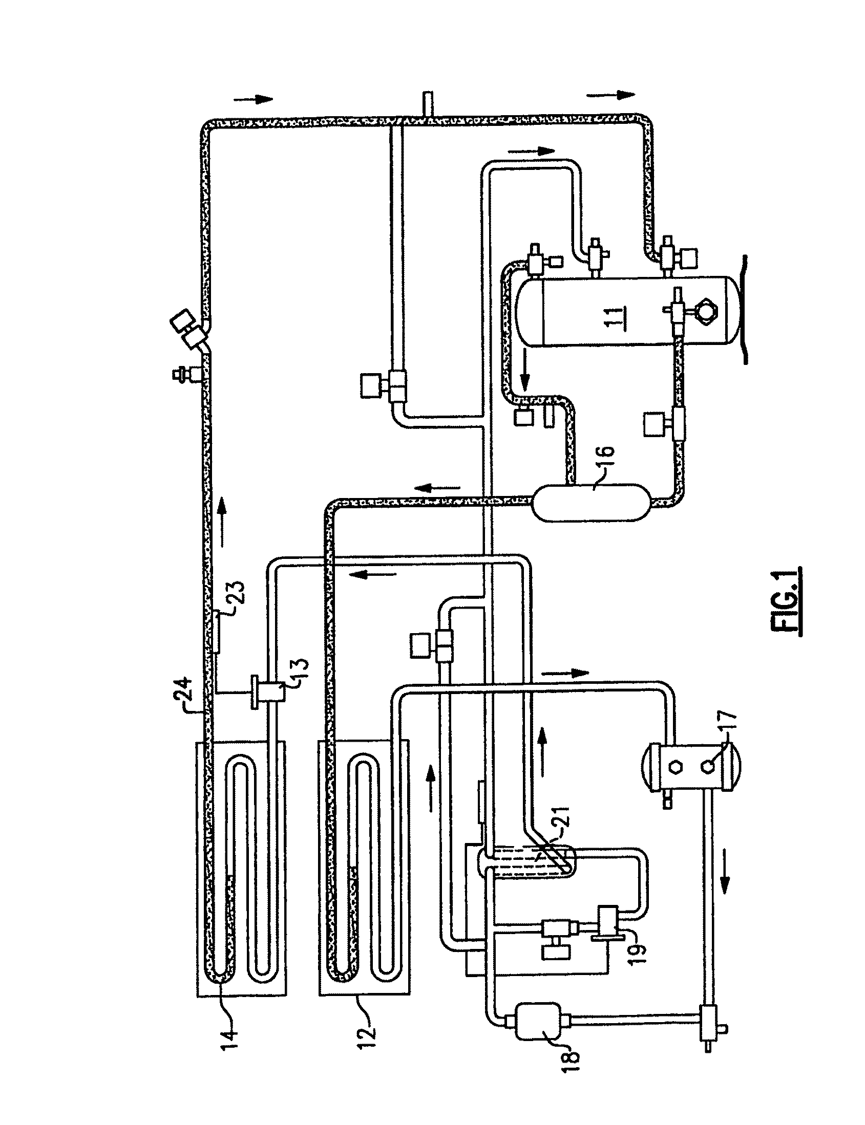
[0015]FIG. 1 is a schematic illustration of a transport refrigeration system of the type to which the present invention is applicable. Connected in typical serial flow relationship are a compressor 11, a condenser 12, an expansion device or thermal expansion valve (TXV) 13 and an evaporator coil 14. The refrigerant is caused by the compressor 11 to flow through the system in a well known manner.

[0016]Other components that are normally included in the system are an oil separator 16, a receiver 17, a filter dryer 18, an economizer TXV 19, and an economizer heat exchanger 21. The oil separator 16 functions to separate the oil from the compressed refrigerant so it can return to the compressor 11. The receiver stores refrigerant for use in low temperature operation. The filter dryer 18 removes moisture and impurities from the refrigerant. The economizer is used to provide frozen range and pull down capacity of the unit by subcooling the liquid refrigerant entering the evaporator TXV 13 w...


PUM

PropertyMeasurementUnit
temperatureaaaaaaaaaa
areaaaaaaaaaaa
temperaturesaaaaaaaaaa

Abstract

A cover for the bulb of a thermal expansion valve is comprised of two halves of an insulative body that are wrapped around the bulb and associated outlet types in clamshell fashion to encapsulate the combination. Internal and external flaps are hingedly connected along their longitudinal edges to permit access for inspection purposes, and the external flap is secured to the internal flap by Velcro. A tongue structure on the outer surface of the body fits into grooves on the inner surface of the outer flap to seal the cover against the entry of moisture. The two halves are secured in place at their ends by way of bands.

Description

BACKGROUND OF THE INVENTION[0001]This invention relates generally to refrigeration systems and, more particularly, to a method and apparatus for insulating and protecting a temperature sensor in a refrigeration system.[0002]In air conditioning and refrigeration systems it is common to maintain a certain degree of superheat in the refrigerant passing from the evaporator to the compressor in order to protect the compressor from damage that can occur by liquid refrigerant passing therethrough. This is accomplished by using a thermal expansion valve upstream of the evaporator coil and an associated temperature sensor or bulb for sensing the temperature of the refrigerant passing from the evaporator coil.[0003]In order for the bulb to provide accurate temperature readings, it is necessary to isolate a bulb and its connection to the outlet line such that water and air currents are not present in the area to provide an inaccurate temperature reading. This has generally been accomplished by...

Claims


Application Information

Patent Timeline
Patent Type & Authority Patents(United States)
IPC IPC(8): G01K1/00G01K13/00
CPCF25D29/005G01K1/143G01K1/08F25B2700/21G01K2201/00
Inventor WEYNA, PAUL V.
Owner CARRIER CORP
Why Eureka
Try Eureka