Insulated temperature sensor

一种温度传感器、传感器的技术,应用在温度计、温度计的应用、温度计的零部件等方向,能够解决成本高、费力等问题

Active Publication Date: 2009-07-29
CARRIER CORP
View PDF0 Cites 4 Cited by
  • Summary
  • Abstract
  • Description
  • Claims
  • Application Information

AI Technical Summary

Problems solved by technology

The problem with this approach is twofold
Both tasks are laborious and costly

Method used


Image

  • Insulated temperature sensor
  • Insulated temperature sensor
  • Insulated temperature sensor

Examples


Embodiment Construction

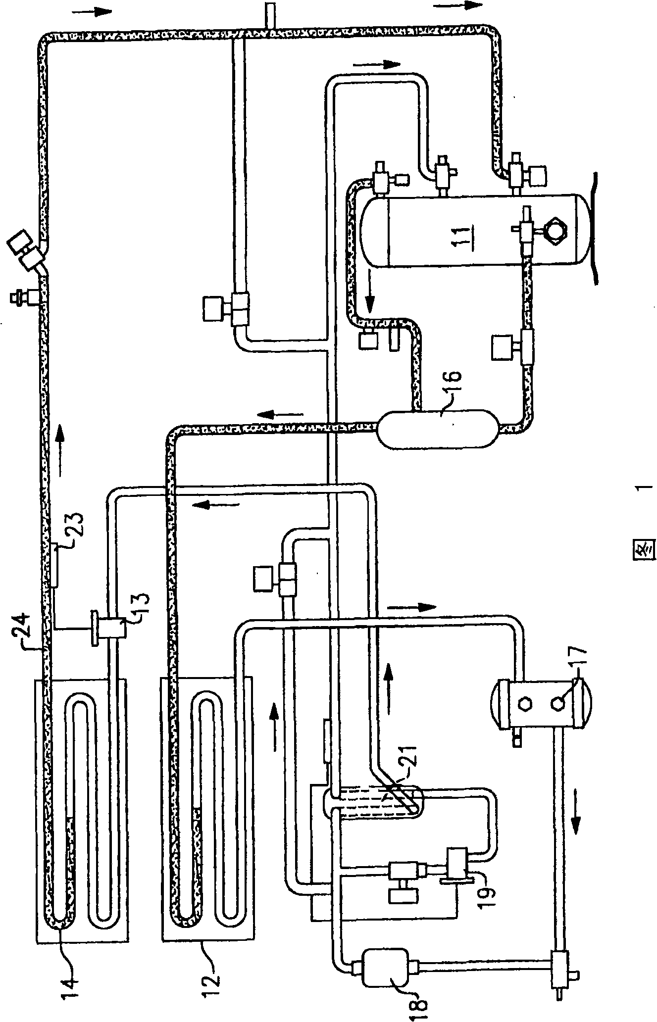
[0015] Fig. 1 is a schematic diagram of a transport refrigeration system to which the present invention can be applied. Connected in representative serial flow relationship are a compressor 11 , a condenser 12 , an expansion device or thermal expansion valve (TXV) 13 , and an evaporator coil 14 . The refrigerant flows through the system under the action of the compressor 11 in a known manner.

[0016] Other components typically included in the system are oil separator 16 , receiver 17 , filter drier 18 , economizer TXV 19 and economizer heat exchanger 21 . The oil separator 16 is used to separate the oil from the compressed refrigerant so that the refrigerant can return to the compressor 11 . The receiver stores refrigerant for low temperature operation. Filter drier 18 removes moisture and impurities from the refrigerant. The economizer is used to provide freezing range and reduced capacity of the unit by subcooling the liquid refrigerant entering the evaporator TXV 13 whe...


PUM


Abstract

A cover for the bulb of a thermal expansion valve is comprised of two halves of an insulative body that are wrapped around the bulb and associated outlet types in clamshell fashion to encapsulate the combination. Internal and external flaps are hingedly connected along their longitudinal edges to permit access for inspection purposes, and the external flap is secured to the internal flap by Velcro. A tongue structure on the outer surface of the body fits into grooves on the inner surface of the outer flap to seal the cover against the entry of moisture. The two halves are secured in place at their ends by way of bands.

Description

technical field [0001] The present invention relates generally to refrigeration systems, and more particularly to a method and apparatus for insulating and protecting temperature sensors within a refrigeration system. Background technique [0002] In air conditioning and refrigeration systems, the refrigerant passing from the evaporator to the compressor is generally kept superheated to some extent in order to protect the compressor from possible damage caused by the passage of liquid refrigerant therethrough. This function is accomplished through the use of a thermal expansion valve located upstream of the evaporator coil and an associated temperature sensor or bulb for sensing the temperature of the refrigerant passing through the evaporator coil. [0003] In order for the bulb to provide accurate temperature readings, it is necessary to isolate the bulb and its connection to the outlet line so that water and drafts cannot be in this area and cause inaccurate temperature r...

Claims


Application Information

Patent Timeline
Patent Type & Authority Applications(China)
IPC IPC(8): G01K1/08
CPCF25D29/005G01K1/143G01K1/08F25B2700/21G01K2201/00
Inventor P·V·维纳
Owner CARRIER CORP
Why Eureka
Try Eureka