Organic electro luminescence display and driving method thereof

a technology of luminescence display and organic electro, which is applied in the direction of electric digital data processing, instruments, computing, etc., can solve the problems of increasing power consumption of organic electro luminescence display, deteriorating picture quality, and increasing power consumption, so as to reduce power consumption and improve outdoor

Active Publication Date: 2012-04-10
SAMSUNG DISPLAY CO LTD
View PDF56 Cites 5 Cited by
  • Summary
  • Abstract
  • Description
  • Claims
  • Application Information

AI Technical Summary

Benefits of technology

[0012]Accordingly, the present invention is designed to solve these and other drawbacks of the prior art, and therefore an object of the present invention is to provide a control unit capable of reducing a power consumption and / or improving an outdoor, and an organic electro luminescence display including the control unit in order to meet the demands of users.
[0015]It is still another object to provide electro luminescent display devices and processes for driving organic electro luminescent display devices, that adjust visibility of the visual images displayed in correspondence with environment of the device.

Problems solved by technology

The power consumption of the organic electro luminescence display is increased however, when a bright light is emitted because the organic electro luminescence display emits light according to the change in electric current capacity, and therefore a low power consumption is necessarily required for applications in various displays.
In order to reduce a power consumption in organic electro luminescence displays in which the light emission level is varied according to the change in electric current capacity, a driving voltage of an image display device should be simply collectively reduced, but when the brightness is lowered in an undesired region of the image, a deterioration in the quality of the picture occurs.
In particular, visibility of the image, displayed in the portable display device using solar light, may be severely reduced if the ambient illumination intensity is greatly brighter than the brightness of the image.

Method used


Image

  • Organic electro luminescence display and driving method thereof
  • Organic electro luminescence display and driving method thereof
  • Organic electro luminescence display and driving method thereof

Examples


Embodiment Construction

[0026]Hereinafter, preferable embodiments according to the present invention will be described with reference to the accompanying drawings. Here, when one element is connected to another element, one element may not only be directly connected to another element but may also be indirectly connected to another element via an intermediate element. Further, immaterial elements are omitted for clarity. Also, like reference numerals refer to like elements throughout.

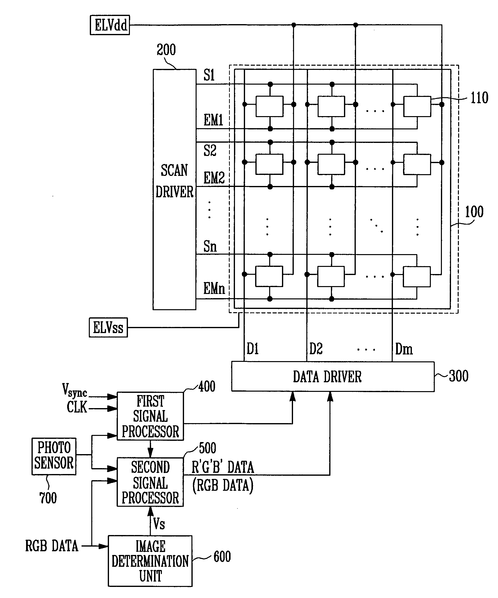
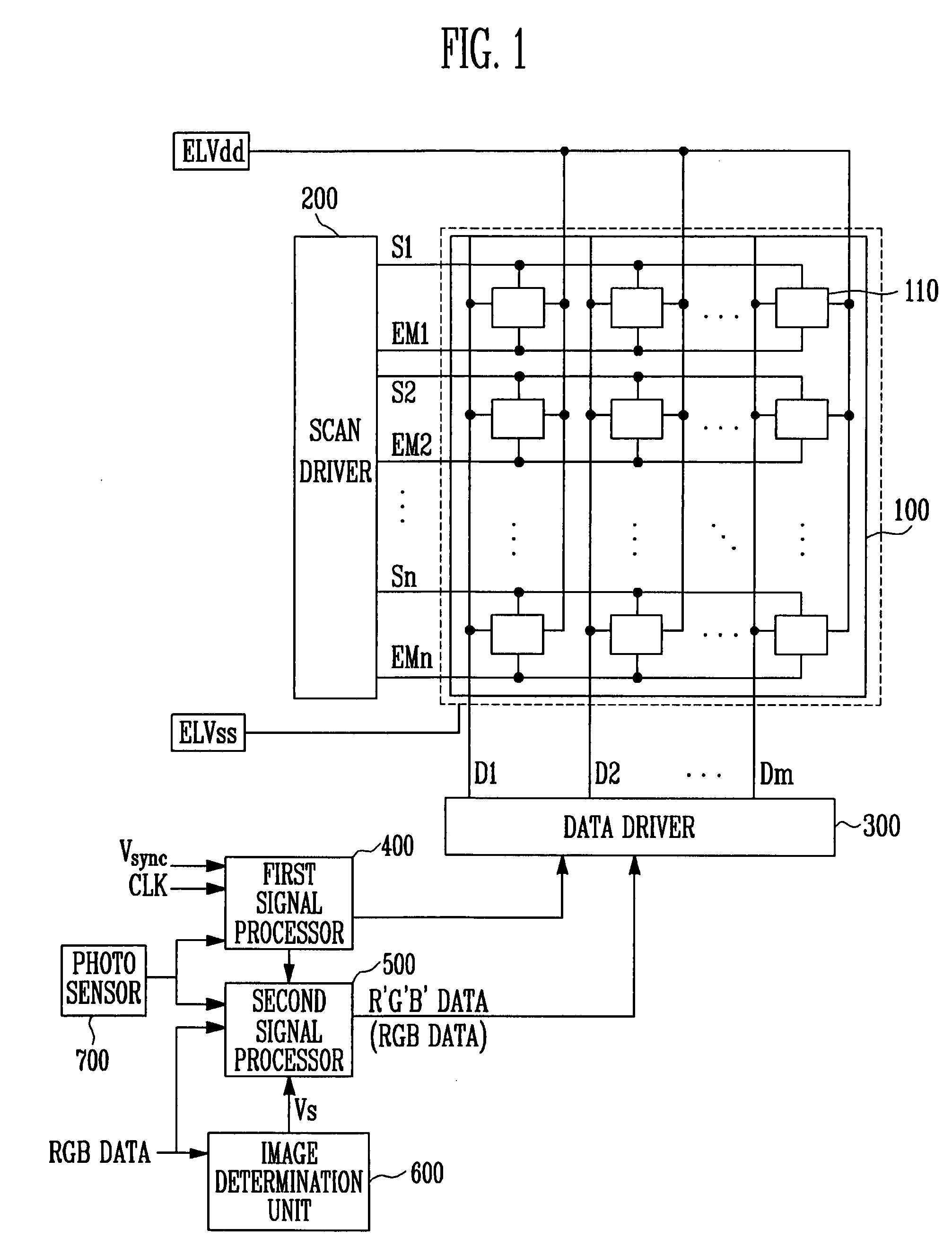
[0027]FIG. 1 is a block diagram illustrating a configuration of an organic electro luminescence display according to one embodiment of the present invention.

[0028]Referring to FIG. 1, the organic electro luminescence display according to one embodiment of the present invention includes a pixel unit 100, a scan driver 200, a data driver 300, a first signal processor 400, a second signal processor 500, an image determination unit 600 and an photo sensor 700.

[0029]Pixel unit 100 includes a plurality of pixels 110 connected to the...


PUM


Abstract

An organic electro luminescence display and driving method uses an image determination unit to generate image determination signals indicative of whether images generated in response to data signals are moving images still images, selects a gamma value corresponding to the brightness of the ambient light sensed, applies gamma correction signals corresponding to selected gamma values to control grey level voltages of the data signals, generates a selection signal based on a comparison of a previously set reference value with the photo sensor signal, and generates R′,G′,B′ data to vary an input image RGB data to correspond to the selection signal, varies a change range of the changing R′,G′,B′ data to correspond to the image determination signal, and supplies the varied change range of the changing data (R′,G′,B′ data) to the data driver.

Description

CLAIM OF PRIORITY[0001]This application makes reference to, incorporates the same herein, and claims all benefits accruing under 35 U.S.C. §119 from an application for ORGANIC LUMINESCENCE DISPLAY AND DRIVING METHOD THEREOF earlier filed in the Korean Intellectual Property Office on the 2 Jan. 2007 and there duly assigned Serial No. 10-2007-0018657.BACKGROUND OF THE INVENTION[0002]1. Field of the Invention[0003]The present invention relates to an organic electro luminescence display, and more particularly to a control unit and a process capable of reducing power consumption and / or improving an outdoor, and an organic electro luminescence display including the control unit.[0004]2. Description of the Related Art[0005]In recent years, there have been may attempts to develop various flat panel displays capable of reducing a weight and volume of a cathode ray tube, which are problematic for cathode ray tubes. The flat panel display includes a liquid crystal display, a field emission dis...

Claims


Application Information

Patent Timeline
Patent Type & Authority Patents(United States)
IPC IPC(8): G09G3/30
CPCG09G3/3208G09G2320/0271G09G2320/0673G09G2320/103G09G2360/144G09G3/30G09G3/20G09G3/32G01J1/40
Inventor PARK, YOUNG-JONGKIM, JONG-SOO
Owner SAMSUNG DISPLAY CO LTD
Why Eureka
Try Eureka