Method and system for the optical measurement of large radii of curvature of optical functional surfaces

a technology of optical functional surfaces and optical measurement systems, applied in the direction of measuring devices, instruments, using optical means, etc., can solve the problems of additional optical elements, measurement setups with refractive measuring lenses, and measurement systems limited to large curvature radii,

Inactive Publication Date: 2012-04-10
JENOPTIK OPTICAL SYST
View PDF5 Cites 4 Cited by
  • Summary
  • Abstract
  • Description
  • Claims
  • Application Information

AI Technical Summary

Problems solved by technology

As to using this system to measure larger radii of curvature, this means that the system described is just as unsuitable as a measuring setup with a refractive measuring lens described above.
Thus, both the optical errors and the alignment errors of the achromat directly influence the surface measurement.
In addition, this measuring system is limited to large radii of curvature and requires an additional optical element, i.e., the achromat.

Method used


Image

  • Method and system for the optical measurement of large radii of curvature of optical functional surfaces
  • Method and system for the optical measurement of large radii of curvature of optical functional surfaces
  • Method and system for the optical measurement of large radii of curvature of optical functional surfaces

Examples


Embodiment Construction

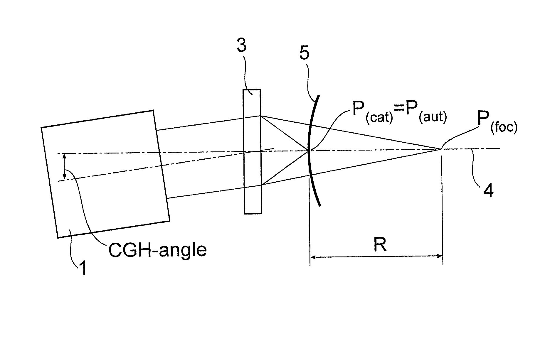
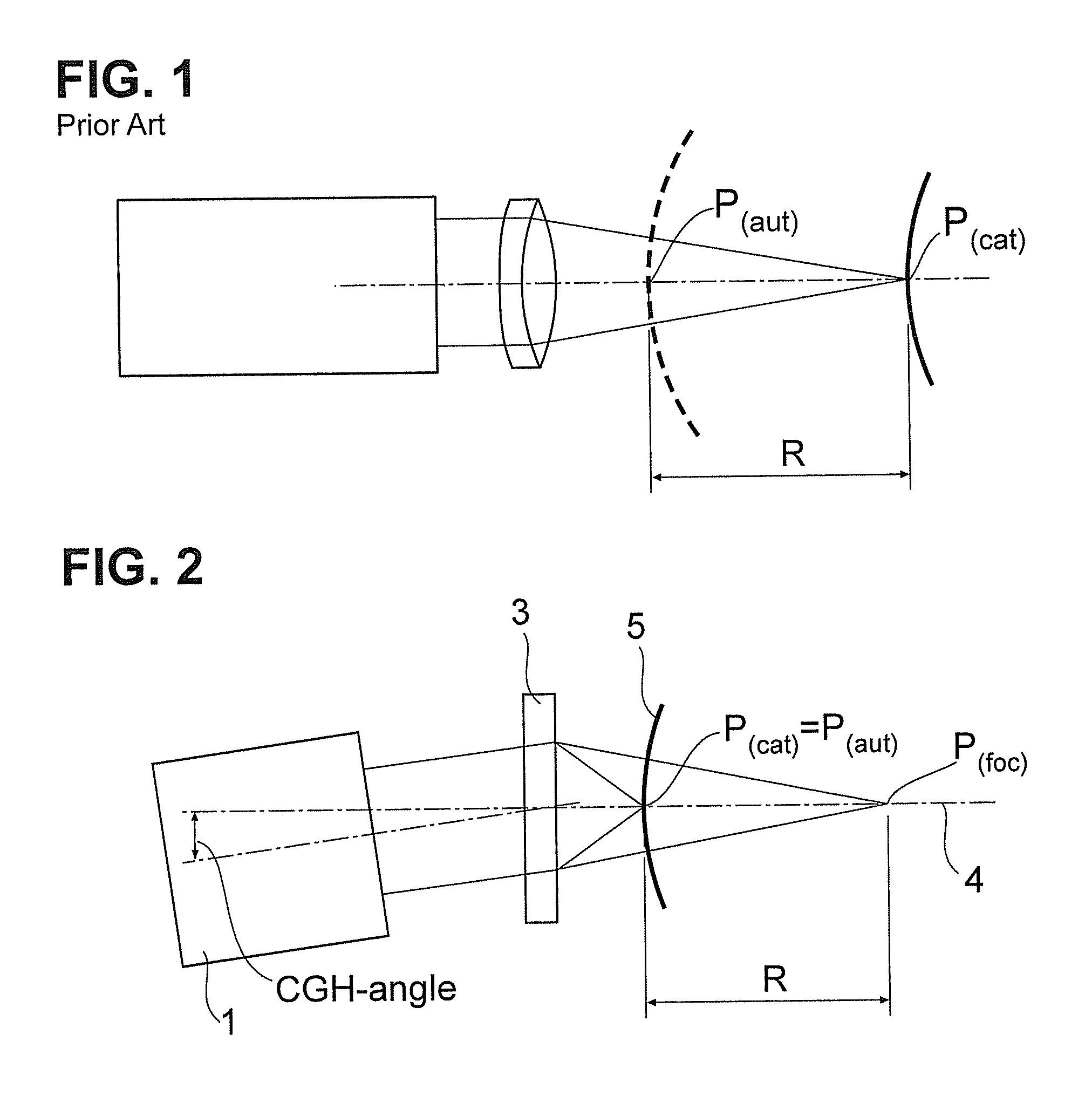
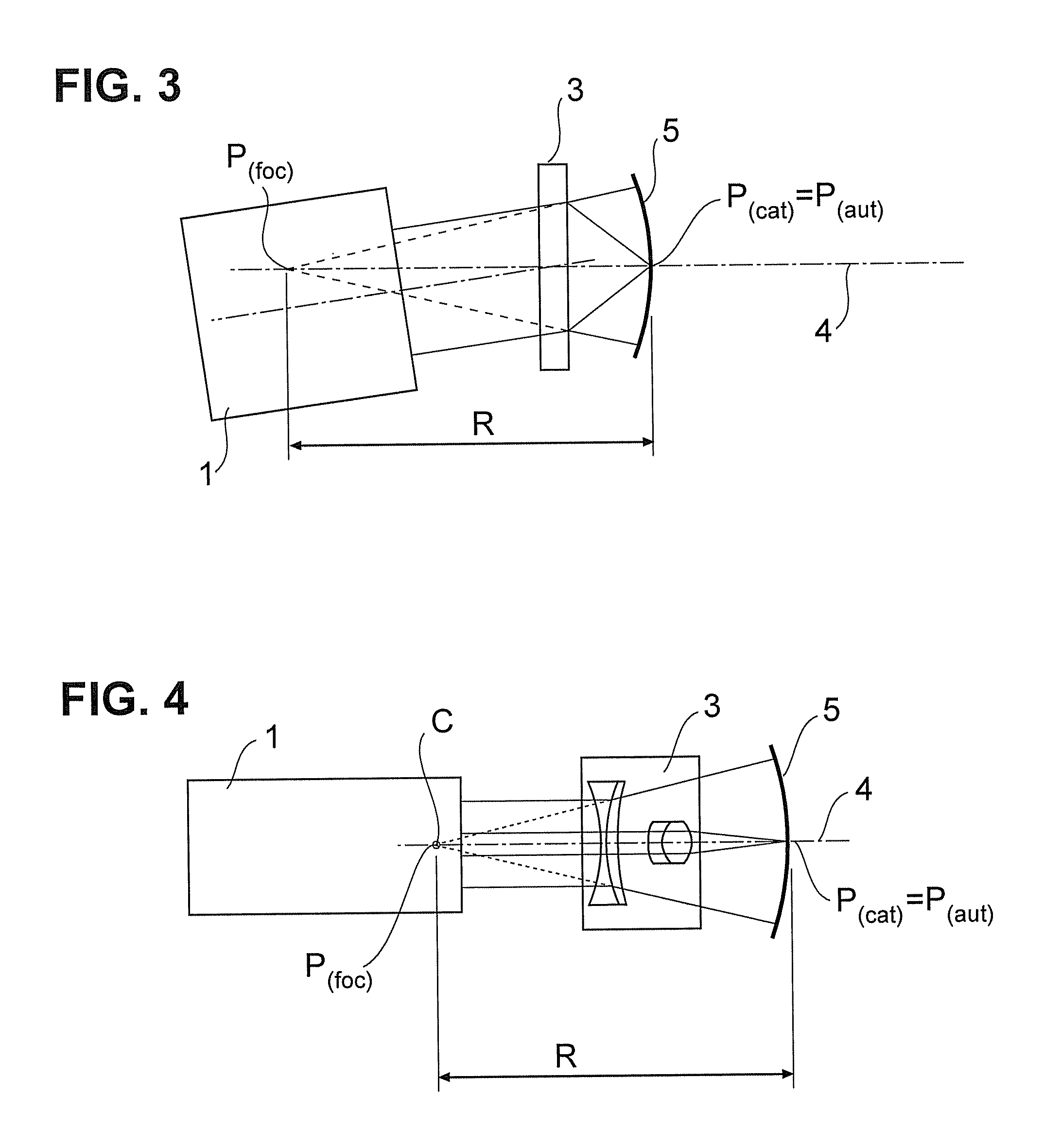
[0046]A system according to the present invention comprises either an interferometer 1 or an autocollimator, either of which, in combination with a supplementary dual-focus lens 3 downstream in the beam direction, is disposed on a common optical axis 4.

[0047]The dual-focus lens can comprise two refractive optical elements, two diffractive optical elements or a combination thereof.

[0048]Depending on the curvature of the test surface 5 (on spherical test surfaces and / or cylindrical test surfaces, this curvature is defined by the radius of curvature R), the focal planes of the dual-focus lens are preferably specified so that their distance D(foc) corresponds to the radius of curvature R. If the system is to be used to test specimens with different radii of curvature R which are within a range of radii of curvatures, the distance between the focal planes D(foc) used is preferably identical to the mean value of the range of radii of curvature through all specimens.

[0049]In all embodiment...


PUM


Abstract

The system and the method of the present invention differ from the prior art in that radii of curvature of any length of spherical and cylindrical test surfaces can be optically measured, with only a supplementary dual-focus lens being required in addition to an interferometer or an autocollimator. The supplementary dual-focus lens has a first focal plane, into which the surface vertex of the test surface is positioned, which establishes the cat's eye position (P(cat)), and a second focal plane into which the center of curvature of the test surface is moved, which establishes the autocollimation position (P(aut)) for the test surface. The radius of curvature of the test surface is determined from the distance between the focal planes (D(foc)) and the path of movement which can be reduced to zero.

Description

FIELD OF THE INVENTION[0001]The subject matter of the present invention relates to a method and a system generically known from the article “Interferometric measurement of spherical mirror surfaces with large radii of curvature,” published in the professional journal Photonik February 2007, pp. 84-85.BACKGROUND OF THE INVENTION[0002]Interferometric measurements of radii of optical functional surfaces (test surfaces) are commonly based on the Fizeau principle. Coherent collimated light from a source is split on an amplitude splitter surface located in the beam path. The reference wave travels back into itself. The test wave is transmitted through the amplitude splitter surface and reaches the specimen. Using a measuring lens, the shape of the wave can be fitted to different specimens. The amplitude splitter surface generally constitutes the last glass-air interface of the lens for spherical specimens. The test wave is generally fitted to the specimen if all beams of the test wave imp...

Claims


Application Information

Patent Timeline
Patent Type & Authority Patents(United States)
IPC IPC(8): G01B11/02
CPCG01B11/2441G01B11/255G01M11/005G01M11/025G01M11/0271G01B9/02039
Inventor FRANZ, STEFANSCHREINER, ROLAND
Owner JENOPTIK OPTICAL SYST
Why Eureka
Try Eureka