

Magnetic field measuring device and method for manufacturing magnetic field measuring device
a magnetic field and measuring device technology, applied in the direction of measuring devices, magnetic measurements, instruments, etc., can solve the problems of difficult to cause the probe, and the plurality of cells are more difficult to adjust the position of the plurality of cells with respect to the incident direction of the probe light, so as to facilitate the adjustment of the position of the second cell
- Summary
- Abstract
- Description
- Claims
- Application Information
AI Technical Summary
Benefits of technology
Problems solved by technology
Method used
Image

Examples
first embodiment
Magnetic Field Measuring Device
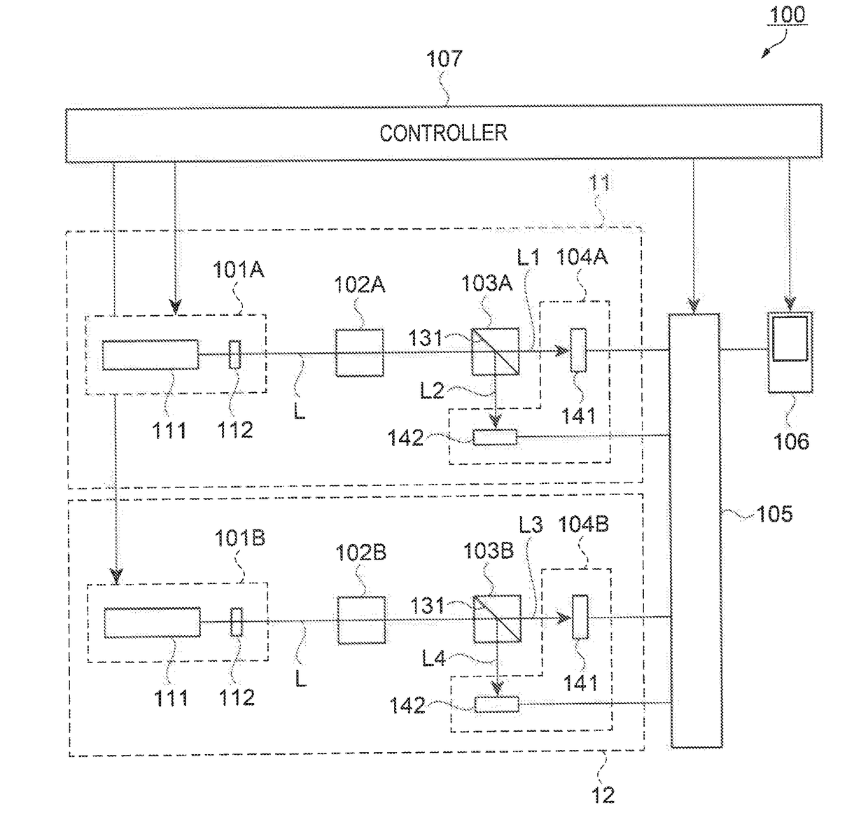
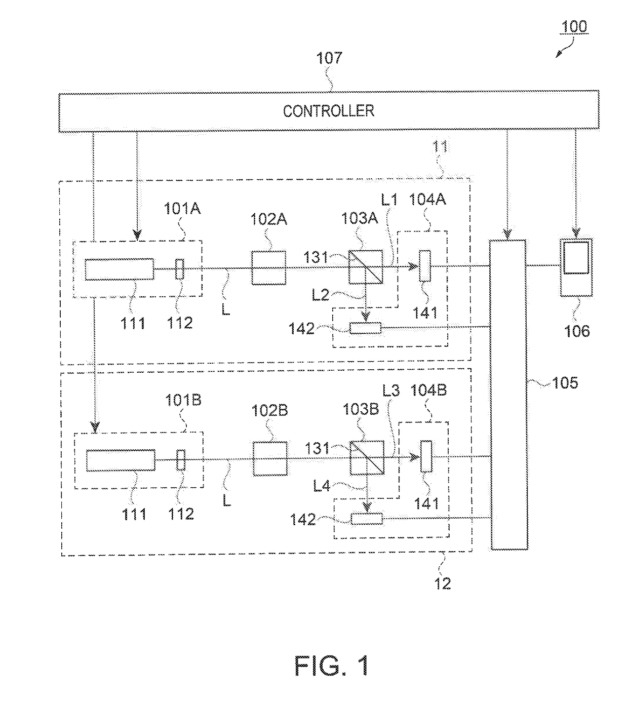
[0043]The magnetic field measuring device of the embodiment is described with reference to FIG. 1. FIG. 1 is a block diagram illustrating a configuration of the magnetic field measuring device of the first embodiment.
[0044]As illustrated in FIG. 1, a magnetic field measuring device 100 of the embodiment includes a measuring magnetic sensor 11, a reference magnetic sensor 12, a signal processing unit 105, a display unit 106, and a controller 107 that collectively controls the sensors and the units. The measuring magnetic sensor 11 is configured to include a first light irradiator 101A, a first cell 102A, a first polarization splitter 103A, and a first light receiving unit 104A. The reference magnetic sensor 12 is configured to include a second light irradiator 101B, a second cell 102B, a second polarization splitter 103B, and a second light receiving unit 104B.
[0045]The magnetic field measuring device 100 irradiates and excites gaseous alkali metal atom...
second embodiment
[0096]FIG. 7 is a schematic diagram illustrating a configuration of a magnetic field measuring device of a second embodiment. Specifically, FIG. 7 corresponds to FIG. 5 in the first embodiment. In the magnetic field measuring device of the second embodiment, the same reference signs are assigned to the same configurations as those in the magnetic field measuring device 100 of the first embodiment, and thus detailed description thereof is omitted. In addition, the magnetic field measuring device of the second embodiment also has basically the gradiometer-type configuration illustrated in FIGS. 1 and 2 of the first embodiment.
[0097]As illustrated in FIG. 7, a magnetic field measuring device 200 of the embodiment includes the first support 108 on which the measuring magnetic sensor 11 is installed, and the second support 109 on which the reference magnetic sensor 12 is installed. The first support 108 and the second support 109 are disposed to overlap each other in the sensing directio...
third embodiment
[0104]FIG. 8 is a plan view schematically illustrating the disposition of the cells in a magnetic field measuring device of a third embodiment, and FIG. 9 is a schematic diagram illustrating the configuration of the magnetic field measuring device of the third embodiment. Specifically, FIG. 9 corresponds to FIG. 5 in the first embodiment. In the magnetic field measuring device of the third embodiment, the same reference signs are assigned to the same configurations as those in the magnetic field measuring device 100 of the first embodiment, and thus detailed description thereof is omitted. The magnetic field measuring device of the third embodiment also has basically the gradiometer-type configuration illustrated in FIGS. 1 and 2 of the first embodiment, and is a magnetic field measuring device that includes the measuring magnetic sensor and the reference magnetic sensor which are configured in multichannel manners, respectively.
[0105]FIG. 8 illustrates disposition of the cells in a...
PUM
 Abstract
Description
Claims
Application Information