Photoelectric autocollimation method and apparatus based on beam drift compensation

a beam drift compensation and autocollimation method technology, applied in the direction of optical radiation measurement, light polarisation measurement, instruments, etc., can solve the problems of limited application of this method, inability to achieve real-time compensation, and limited measurement uncertainty, so as to achieve high autocollimation angle measurement accuracy

Inactive Publication Date: 2013-04-04
HARBIN INST OF TECH
View PDF1 Cites 16 Cited by
  • Summary
  • Abstract
  • Description
  • Claims
  • Application Information

AI Technical Summary

Benefits of technology

[0022]One purpose of this invention is to provide a photoelectric autocollimation method and apparatus based on beam drift compensation, which can be used to achieve high autocollimation angle measurement accuracy.

Problems solved by technology

But their measurement uncertainty is mainly limited by the drift of laser beam, which increases as the measurement distance increases.
(1) Spatial connection lines of diffraction or interference fringes generated by zone plates, phase plates, binary optic elements or double slits, can be used to restrain beam drift. For example, a zone plate can be used to generate a bright cross reticle on the line connecting laser light source and zone plate center. The cross reticle can be imaged at different positions along the optical axis, by adjusting a telescope between laser light source and zone plate. So the optical axis can be used as a datum line and can be traced by the cross reticle. Because the reticle is generated by diffraction and interference, it has a good anti-interference performance and it can therefore reach a measurement accuracy of + / −1×10⁻⁷ rad (0.04 arcsecond). However, this method requires constant adjustment of the telescope to move the reticle along the optical-axis, and so, it cannot be used to achieve real-time compensation. For this reason, the application of this method is limited.
However, this method cannot be used to restrain the angular drift of incident light.
However, the generation of symmetrical dual beams needs multiple reflections and refractions, which increase the difficulties of processing and installing optic components.
In addition, the two symmetrical beams have different drifts due to the noncoincidence of two beam paths, which restrains the effect of compensation for the drift caused on the beam path.
But this method is mainly appropriate for measurement of straightness, and it is difficult to use it for measurement of angles, because of the parallel and reversely reflective properties of a cube-corner reflector.
The drift of compensation beam can not completely represent the drift of measurement beam, which leads to a poor compensation effect.
But this method is used to enhance the directional stability of laser beam only, and it cannot be used for measurement of angles.
However, this system can only used for alignment of laser beam in a given direction.
However, the measurement and reference beams used in this method are not on a common path during returning.
The feedback control system cannot effectively restrain the drift of measurement beam, and so, the final angle measurement accuracy is restrained.
(1) The method of using spatial connection lines of diffraction or interference fringes requires high directional stability of the incident beam, and it cannot restrain the angular drift of the incident beam. The angular drift of incident beam results to the drift of the spatial connection lines which is used as the datum line. Moreover, this method has a limited capability of restraining the air disturbance in the beam path.
(2) The generation of the symmetrical dual beams in the methods of dual beams compensation is difficult. And the measurement and reference beams used in this method are not on a common path, and so, the drift of reference beam cannot completely represent the drift of measurement beam, which results to poor compensation effect.
(3) The close-loop feedback control method is mainly used to enhance the stability of laser beam in a given direction, and it is difficult to be used for measurement of angles. Moreover, the reference and measurement beams cannot transmit on a common path, and so the drift of reference beam is not completely the same as the drift of measurement beam, which results to poor compensation effect.

Method used


Image

  • Photoelectric autocollimation method and apparatus based on beam drift compensation
  • Photoelectric autocollimation method and apparatus based on beam drift compensation
  • Photoelectric autocollimation method and apparatus based on beam drift compensation

Examples


embodiment 1

Preferred Embodiment 1

[0078]As shown in FIG. 17, the proposed photoelectric autocollimation method based on beam drift compensation, which employs a reference mirror to reflect the reference beam, comprises following steps:

[0079]S101: A collimated beam is formed by passing a polarized beam emitted from a laser source through a reticle, a polarization-insensitive beamsplitter and a collimating lens successively;

[0080]S102: The collimated beam is reflected by a beam steering device into a first polarizing beamsplitter, which split it into a polarized transmitted beam and a polarized reflected beam, so that both the transmitted and reflected beams are polarized with the polarization states mutually perpendicular to each other;

[0081]S103: The polarized transmitted beam obtained in S102 is reflected by a measurement mirror, and then formulated as a measurement beam. The described measurement beam carries the two-dimensional angular deflection information of the measurement mirror and the...

embodiment 2

Preferred Embodiment 2

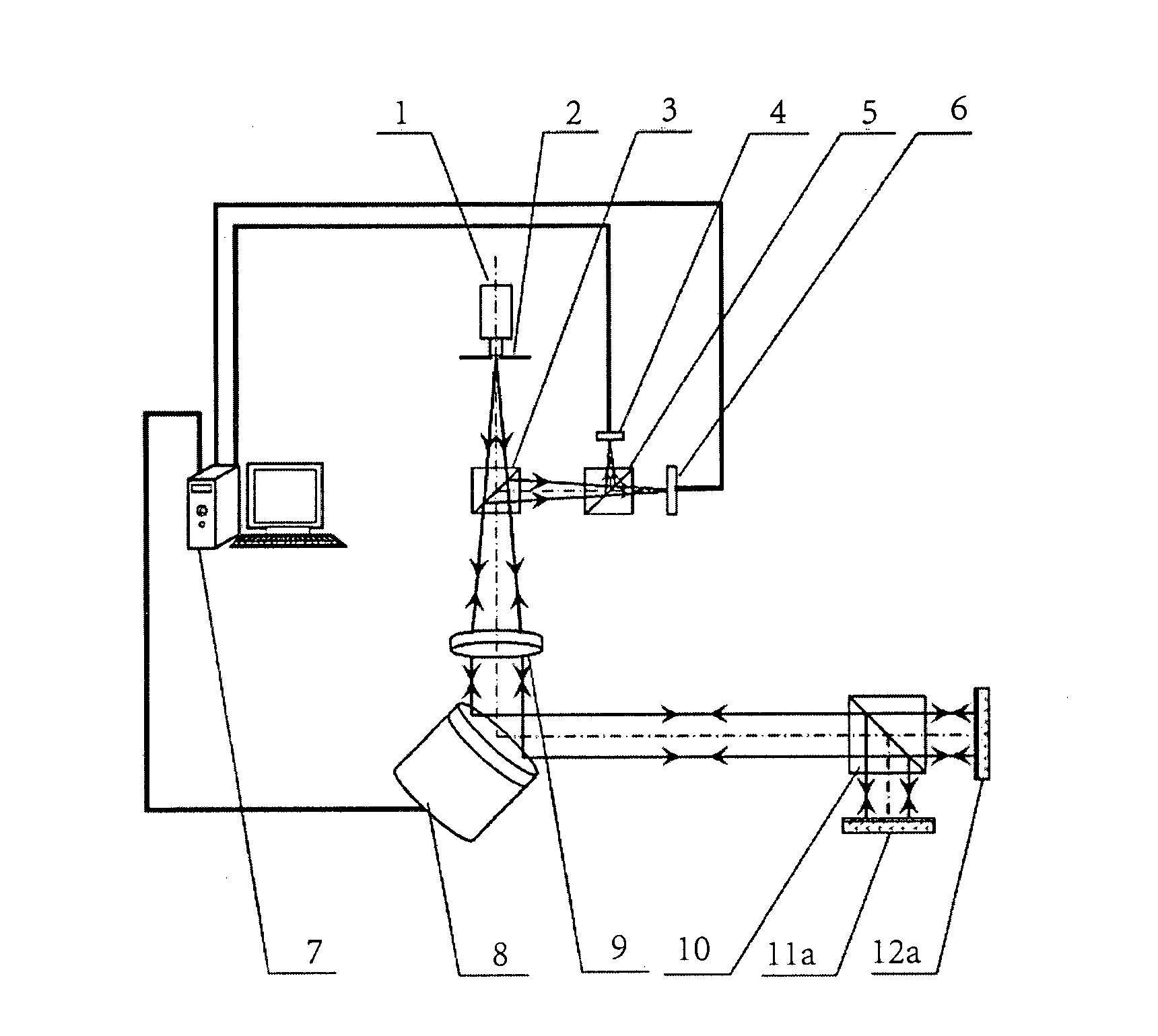
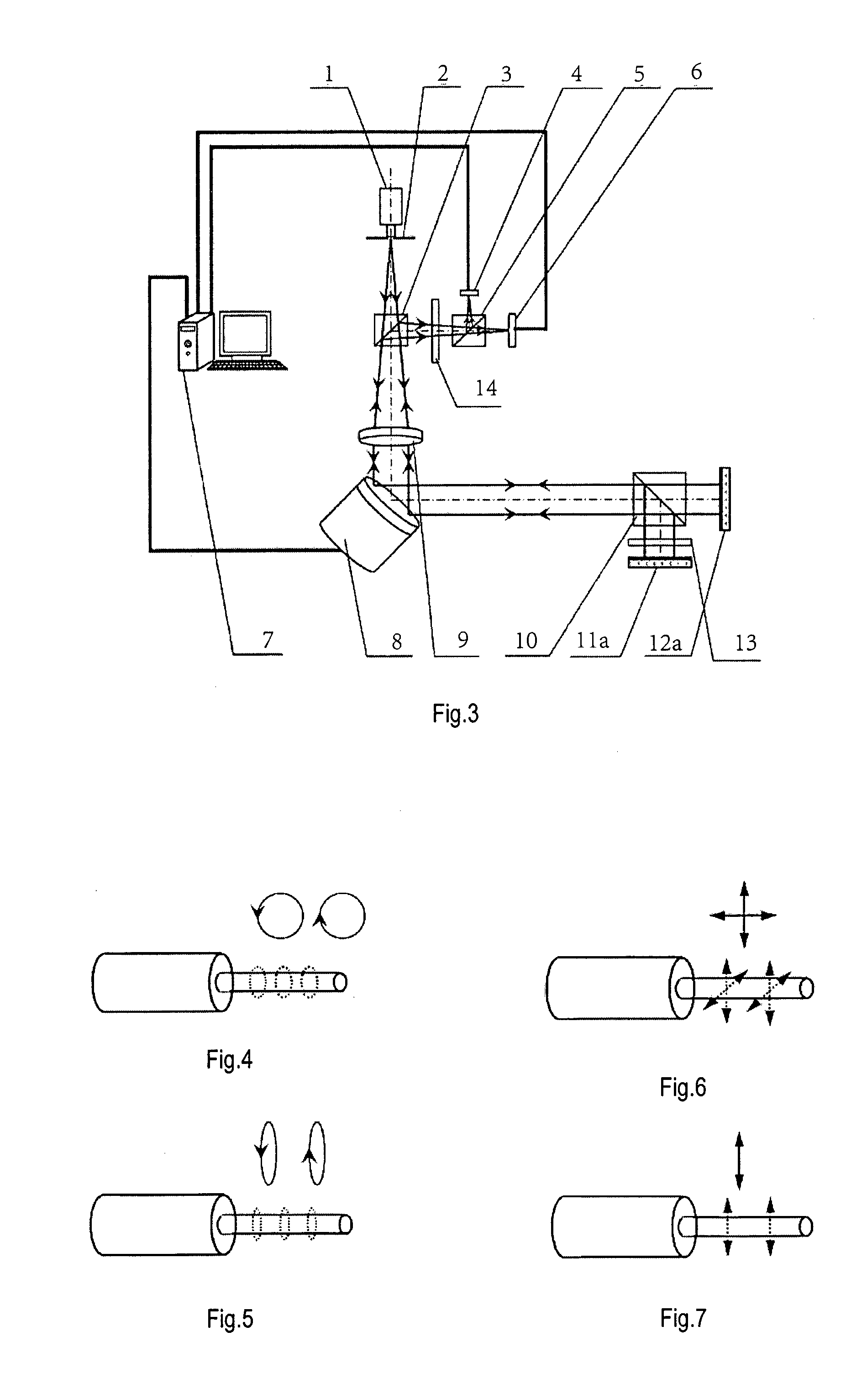
[0087]As shown in FIG. 1, the photoelectric autocollimation apparatus based on beam drift compensation, which employs a reference mirror to reflect the reference beam, mainly comprising an autocollimator, a beam steering device 8, a measurement mirror 12a, a data processing controller 7 and a beam drift monitoring and separating unit based on reference mirror 11a:

[0088]The autocollimator mainly comprising a laser source 1, a reticle 2, a polarization-insensitive beamsplitter 3, collimating lens 9 and a first photoelectric position sensor 6 which is positioned on the focal plane of the collimating lens 9 in the reflection direction of the polarization-insensitive beamsplitter 3. The output signal of the first photoelectric position sensor 6 is transferred to the data processing controller 7, which calculates the angular deflection of the measurement mirror 12a according to this output signal.

[0089]A beam steering device 8 is positioned right in front of collima...

embodiment 3

Preferred Embodiment 3

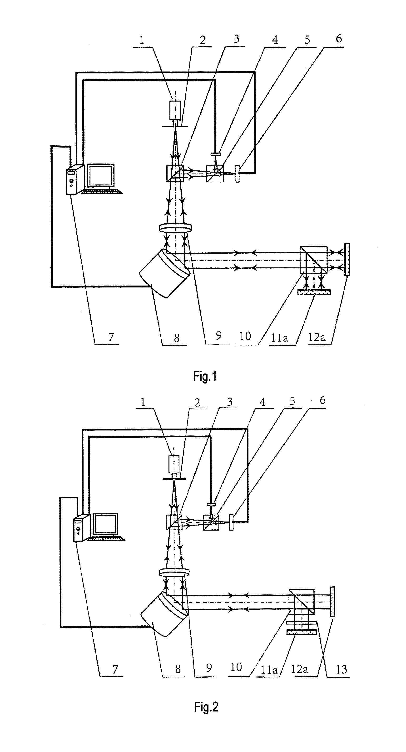
[0094]As shown in FIG. 2, this embodiment includes a first ¼ wave plate 13, and in this embodiment the first polarizing beamsplitter 10 is replaced by a second polarization-insensitive beamsplitter 10. In this embodiment, all the other constitutions remain the same as those in preferred embodiment 2. The first ¼ wave plate 13 is positioned between the second polarization-insensitive beamsplitter 10 and the reference mirror 11a. The laser beam emitted from the laser source 1 is a linear polarized beam as shown in FIG. 7 with the polarization plane coincident with the transmitted polarization plane of the second polarizing beamsplitter 5.


PUM


Abstract

Photoelectric autocollimation methods and apparatuses based on beam drift compensation are provided. The methods and apparatuses can be used to achieve a high autocollimation angle measurement accuracy. The apparatuses includes an autocollimator, a measurement mirror (12a), a beam drift monitoring and separating unit, a beam steering device (8), and a data processing controller (7). The beam drift monitoring and separating unit generate a reference beam with the same drift as the measurement beam. The measurement beam carries both angular deflection information of the measurement mirror and the angular beam drift information, while the reference beam carries only the angular beam drift information. The data processing controller gives out a signal to the beam steering device in real-time according to the magnitude of drift of the reference beam, to compensate the drift of the measurement beam.

Description

TECHNICAL FIELD OF THE INVENTION[0001]This invention relates to a photoelectric autocollimation method and apparatus which can be used to achieve high autocollimation angle measurement accuracy.BACKGROUND ARTS[0002]Photoelectric autocollimator is widely used for measurement and calibration of small angles, flatness measurement of plates, sway angle measurement of axises, straightness measurement of slides, and position uncertainty measurement of rotary tables, etc. in the fields of mechanical manufacturing, shipbuilding, aerospace, and Scientific Research, etc.[0003]Laser is often used for long-distance and high-precision measurement of angles because of its monochromaticity and high energy density. Many high-precision photoelectric autocollimators have been developed with laser used as light source. But their measurement uncertainty is mainly limited by the drift of laser beam, which increases as the measurement distance increases.[0004]The uncertainty of most photoelectric autocol...

Claims


Application Information

Patent Timeline
Patent Type & Authority Applications(United States)
IPC IPC(8): G02B27/30
CPCG02B5/122G02B27/30G02B27/283G01B11/26G02B27/28
Inventor TAN, JUIBINZHU, FANCUI, JIWEN
Owner HARBIN INST OF TECH
Why Eureka
Try Eureka