
LED display module having a metallic housing and metallic mask

a technology of led display module and metallic housing, which is applied in the direction of modification by conduction heat transfer, gas-filled discharge tube, lighting support devices, etc., can solve the problems of fast led degradation and failure, disruption of display viewing at moderate or extreme angles, etc., and achieve the effect of reducing heat dissipation, distributing heat and dissipation

Inactive Publication Date: 2012-04-10
DAKTRONICS
View PDF25 Cites 120 Cited by
  • Summary
  • Abstract
  • Description
  • Claims
  • Application Information

AI Technical Summary

Benefits of technology

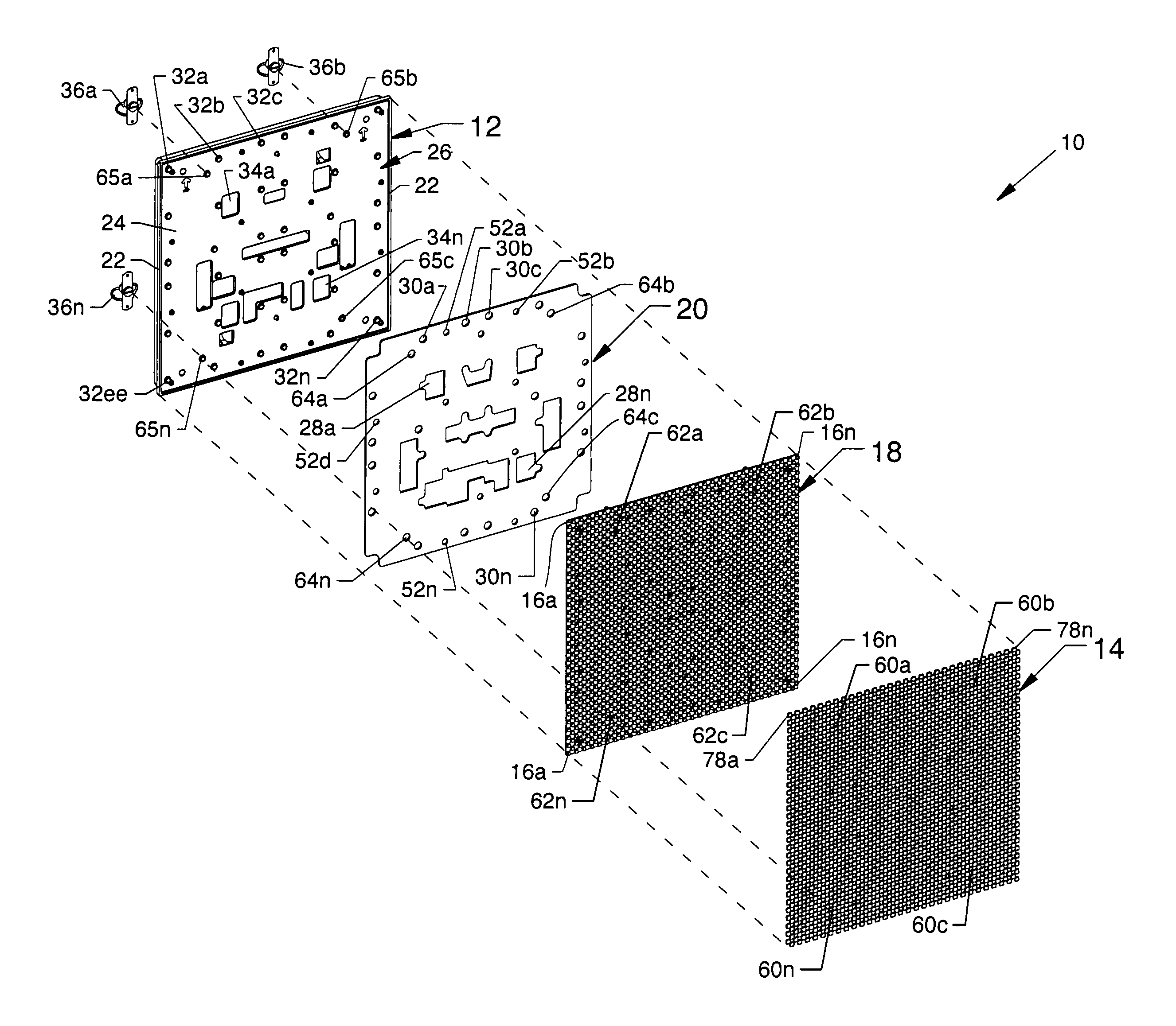
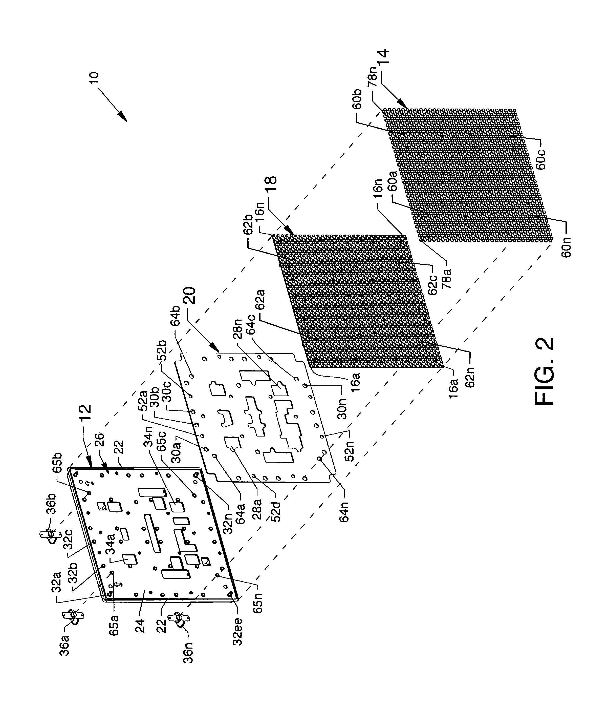
[0007]The general purpose of the present invention is to provide an LED display module having a metallic housing and a metallic mask in order to evenly distribute, reduce and dissipate heat, to provide EMI protection, to provide for durability and rigidity, to increase viewability and to extend component life, as well as other benefits which may be described herein. The present invention features a plurality of closely aligned components including, but not limited to, a housing made of a metallic material, a heat conductive interface panel, an LED circuit board having a plurality of LEDs attached thereto, and a mask made of a metallic material through which the LEDs of the circuit board extend. The rear of the metallic housing includes a plurality of cooling fins for dissipating heat from the body of the metallic housing, which heat is generated by other components including, but not limited to, the plurality of LEDs. The metallic housing also includes multiple features for accommodating the mutual fastening of components of the present invention and for accommodating the fastening of the LED display module to a mounting panel of an electronic sign. The heat conductive interface panel is aligned between the metallic housing and the LED circuit board in order to transfer LED generated heat residing in the LED circuit board for dissipation by the metallic housing in combination with dissipation provided by the cooling fins. The metallic mask fittingly accommodates the plurality of LEDs and serves to draw off heat from the LEDs which are shown as multiple colored LED packages. The use of metallic components and features which draw off and dissipate heat provides for a structurally stable device which diminishes and / or eliminates panel warpage and which provides for EMI prevention.
[0008]According to one or more embodiments of the present invention, there is provided an LED display module having a metallic housing, a heat conductive interface panel, an LED circuit board, and a metallic mask arranged preferably in intimate contact and association with each other in order to evenly distribute, reduce and dissipate heat. A plurality of fasteners extend through the intimately engaged arrangement of components to forcibly ensure sufficient mutual surface contact in order to efficiently, effectively and evenly distribute, reduce and dissipate heat. Such fastening also ensures an electrical and physical connection between the metallic housing and the metallic mask in order to effect an EMI proof enclosure as provided by the present invention. A plurality of helical spring latches located at the rear of the metallic housing are provided for attachment of the present invention to a mounting panel of an electronic sign and also to assist in heat transfer to the mounting panel.

Problems solved by technology

The increased temperatures cause faster LED degradation and failure.
Such expansion due to increased temperatures resulted in warping and disruption of display viewing at moderate or extreme angles.
Other concerns associated with LED display modules is that of electromagnetic interference (EMI) with other electronic devices, such as caused by electronic circuitry used within an LED display module where prior art housings and masks were comprised of plastic components.

Method used


Image

  • LED display module having a metallic housing and metallic mask
  • LED display module having a metallic housing and metallic mask
  • LED display module having a metallic housing and metallic mask

Examples


Embodiment Construction

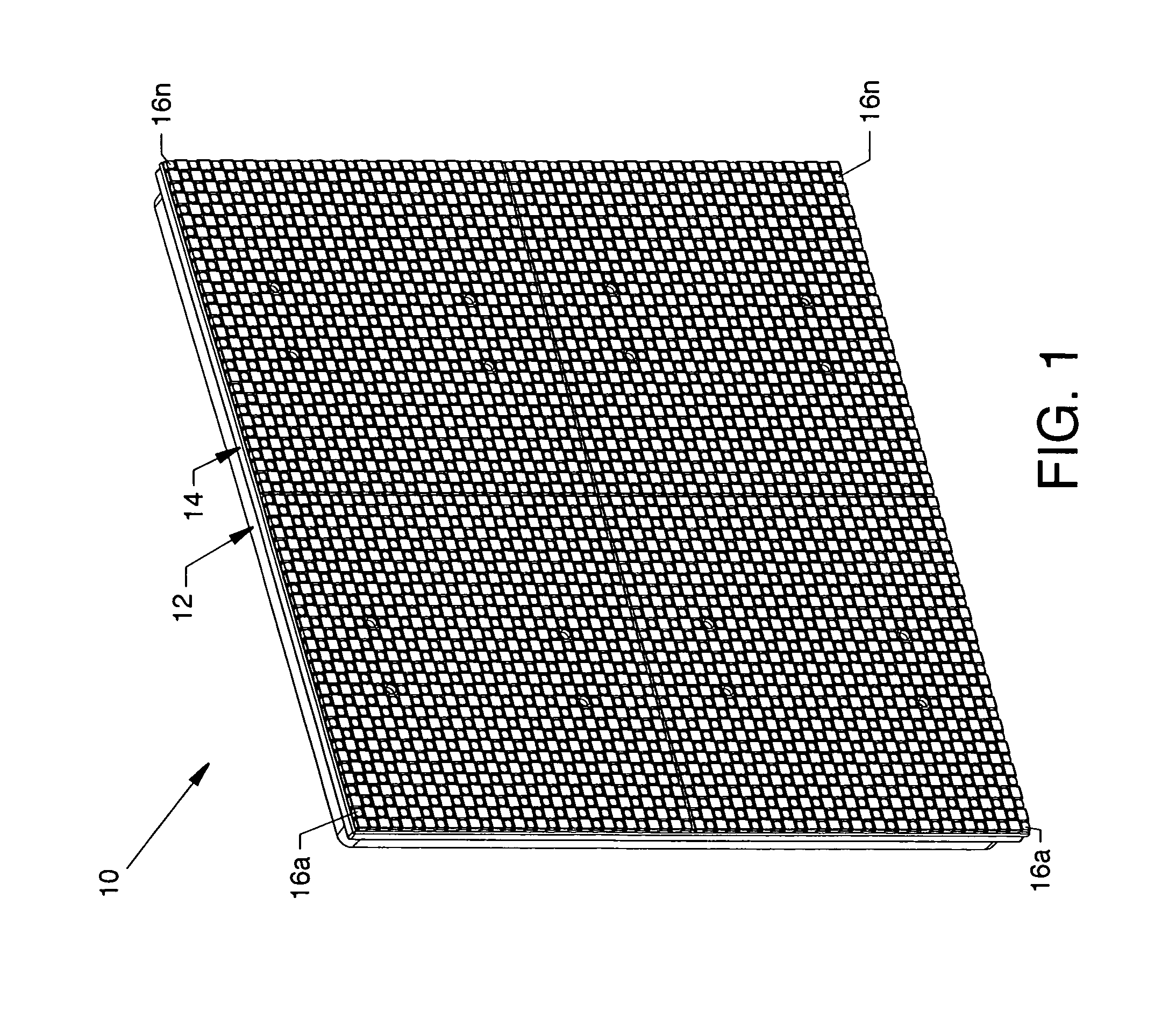
[0033]FIG. 1 is a front isometric view of an LED display module 10, the present invention, having and including a metallic housing 12 and a metallic mask 14, the general shape thereof preferably being that of, but not limited to, a square. The metallic mask 14 is comprised of four closely aligned separate mask panels which are referred to unitarily as the metallic mask 14. In the alternative, the metallic mask 14 can be of single mask panel construction. A plurality of multiple color LED pixel packages are referred to herein as LEDs 16a-16n. The LEDs 16a-16n are uniformly spaced and distributed in multiple staggered rows along and about and in accommodation by the metallic mask 14, as later described in detail.

[0034]FIG. 2 is an exploded front isometric view of the LED display module 10 of FIG. 1, where all numerals correspond to those previously described. The metallic housing 12 and the metallic mask 14 are made of a metal material such as, but not limited to, magnesium or a combi...


PUM


Abstract

The present invention is a robust LED display module for use in an electronic sign which display module includes a metallic housing, a heat conductive interface panel, an LED circuit board and LEDs, and a metallic mask arranged in intimate contact and association therewith, and which components operate synergistically in concert with each other in order to evenly distribute, reduce and dissipate heat along, about and within the structure of the present invention. Display uniformity is provided by the use of major metallic structures in order to prevent warpage and to protect the geometric integrity of the LED display module.

Description

CROSS REFERENCES TO RELATED APPLICATIONS[0001]This application claims priority from the earlier filed U.S. Provisional Application No. 60 / 993,908 filed Sep. 14, 2007, entitled “Metallic Module and Mask for LED Display”, and is hereby incorporated into this application by reference as if fully set forth herein.[0002]This patent application is also related to patent application Ser. No. 10 / 459,952 filed on Jun. 12, 2003, entitled “LED Module Latch System”, which is now U.S. Pat. No. 6,816,389.BACKGROUND OF THE INVENTION[0003]1. Field of the Invention[0004]The present invention is for an LED display module, and more particularly, is for an LED display module having a metallic housing and mask.[0005]2. Description of the Prior Art[0006]Pixel spacing for light emitting diode (LED) displays has become smaller based on the need for higher resolution. To meet this demand, the use of more LEDs per unit area is required. The increase in LED density causes increased heat generation and, theref...

Claims


Application Information

Patent Timeline
Patent Type & Authority Patents(United States)
IPC IPC(8): H05K7/20F21S2/00
CPCG09F9/33H05K7/2039G09F9/3026
Inventor NEARMAN, NATHAN L.MUTSCHELKNAUS, SHANNON LEEMUELLER, MATTHEW R.TVEDT, DOUGLAS P.MILLER, KENT S.DENNIS, MARK D.HAGE, JOHN L.NIELSEN, RYAN J.
Owner DAKTRONICS
Learn More