Control method of traveling dolly

a control method and dolly technology, applied in adaptive control, instruments, tractor and other directions, can solve the problems of difficult convergence, low efficiency, and low efficiency, and achieve the effect of easy on and off, and easy operation by the operator

Inactive Publication Date: 2012-04-10
TOYOTA JIDOSHA KK
View PDF24 Cites 23 Cited by
  • Summary
  • Abstract
  • Description
  • Claims
  • Application Information

AI Technical Summary

Benefits of technology

[0016]Accordingly, by calculating the control command value based on the target body tilt angle, dummy body tilt angle becomes zero so that the dolly can stops at the initial position even if the external force is applied. Namely, even if large external force is applied on the body, the dolly (the position of the wheel) is not moved and the position can be controlled stably at the place, whereby an operator can get on and off easily and goods can be taken on and off easily.
[0047]Accordingly, the moving distance from the time that the external force applied on the body by the disturbance to the time that the traveling dolly is stopped stably is shorten. Accordingly, for example in the two-wheel state of the traveling, goods can be taken on and off easily and an operator can get on and off easily.

Problems solved by technology

Accordingly, trade-off (the relation that if one of conditions is satisfied, the other condition becomes dissatisfied) exists between the two outputs, and if the disturbance applied on the dolly is large, below problems may be caused.
However, for example when the external force caused by the large disturbance which is stationary or changes transiently widely is applied on the body, the body tilt angle and the wheel angle cannot be made zero simultaneously, whereby the oscillation centering on the initial position (the position of the dolly before applying the disturbance thereon) is difficult to be converged.
Furthermore, according to the same reason, if an operator jumps on the traveling dolly or similar operation is performed on the dolly, the position of the wheel must be moved widely and an operator cannot get on and off easily.
Considering such a traveling dolly as a mobile body on which an operator rides or which carries goods, the occurrence of large movement of the wheel position by the disturbance makes an operator difficult to get on and off and makes goods difficult to be taken on and off.

Method used


Image

  • Control method of traveling dolly
  • Control method of traveling dolly
  • Control method of traveling dolly

Examples


Embodiment Construction

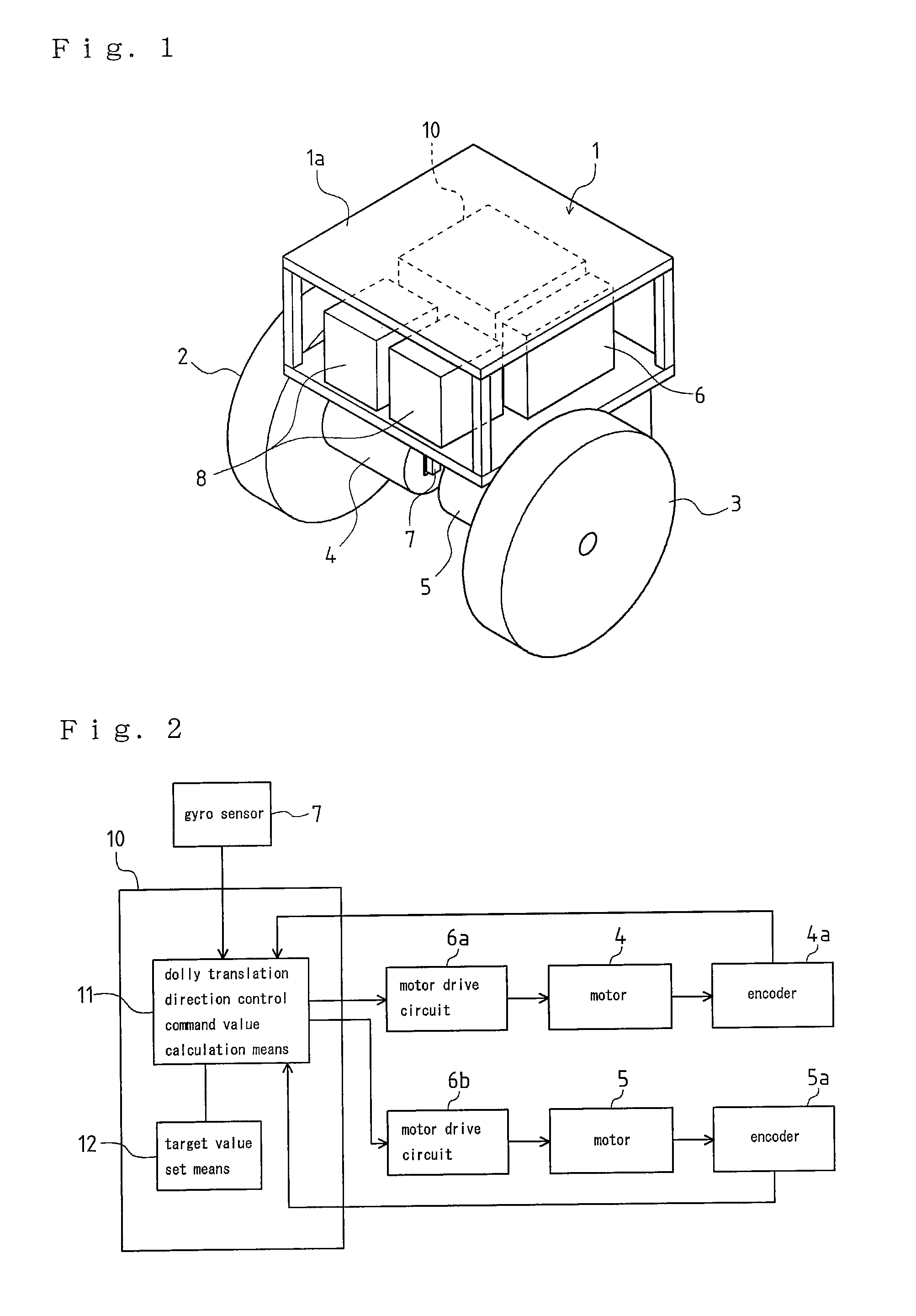
[0052]Firstly, explanation will be given on schematic construction of an example of a traveling dolly according to the present invention by reference to FIG. 1.

[0053]The traveling dolly according to the present invention has left and right wheels 2 and 3 disposed in a lower portion of a main body of the dolly (hereinafter, referred to as “body”) 1 formed by framing to substantial rectangular hexahedral shape. The wheels 2 and 3 are arranged on the same rotation axis bilaterally symmetrically, and the body 1 can be tilted to the direction perpendicular to the rotation axis.

[0054]A motor 4 as a driving means is connected to the right wheel 2, and a motor 5 as a driving means is connected to the left wheel 3. Encoders 4a and 5a (see FIG. 2) are attached to the motors 4 and 5 respectively so as to detect rotation speed thereof.

[0055]A single-shaft gyro sensor 7 is arranged along the direction perpendicular to the rotation axis of the wheels 2 and 3 (the tilt direction of the body 1). Th...


PUM


Abstract

A control method is proposed for a traveling dolly. The traveling dolly may include wheels driven by motors and a body supported by the wheels. The traveling dolly may further include a control computer commanding control command value to the motors, and a centroid of the body positioning above a rotation axis of the wheels. The control method may include the control computer estimating external force moment, which is a moment of inertia around the rotation axis of the wheels generated by external force applied on the body; a tilt angle of the body, which makes a gravity moment around the rotation axis of the centroid of the body balance with the external force moment, being set as a target body tilt angle; and based on the target body tilt angle, calculating a torque command value for the motors.

Description

FIELD OF THE ART OF THE INVENTION[0001]The present invention relates to control method of an inverted pendulum-type traveling dolly that a centroid of the body positions above a rotation axis of a wheel. The present invention also relates to the traveling dolly.BACKGROUND ART[0002]With regard to an inverted pendulum-type traveling dolly and control method thereof, for example, there is known an art described in the Japanese Patent Laid Open Gazette 2004-295430.[0003]In the Japanese Patent Laid Open Gazette 2004-295430, a traveling dolly is disclosed which has a wheel and a body supported by the wheel, a centroid of the body positioning above a rotation axis of the wheel. With regard to the traveling dolly, control at the dolly translation direction (the direction rectangular to the axis) including the inverted pendulum control and the position control and control at the dolly rotation direction (the turning direction of the axis) including only the position control are performed.[00...

Claims


Application Information

Patent Timeline
Patent Type & Authority Patents(United States)
IPC IPC(8): G06F17/00
CPCB62K17/00G05D1/0891Y02T10/7258B60L15/20B60L2200/28B60L2220/46B60L2240/18B60L2240/20B60L2240/24B60L2240/423B60L2260/34Y02T10/72Y02T10/64G05B13/02
Inventor FUWA, TOSHIONAKASHIMA, ISSEI
Owner TOYOTA JIDOSHA KK
Why Eureka
Try Eureka