
Filter with bayonet coupling to cover

a technology of bayonets and filters, applied in the field of filters, can solve the problems of friction and wear at the sealing location of the filter element, the risk of seal wear on the filter element, and the danger of internal leakage from the unfiltered to the filtered side or the return flow, etc., and achieve the effect of simple production and low cos

Inactive Publication Date: 2012-04-17
MANN HUMMEL GMBH
View PDF10 Cites 27 Cited by
  • Summary
  • Abstract
  • Description
  • Claims
  • Application Information

AI Technical Summary

Benefits of technology

The present invention provides a way to decouple a filter element from its filter lid in a simple and inexpensive way. This is achieved by using a filter housing with a first thread and a drain passage, onto which a filter lid is screwed with a second thread. A filter bypass valve is provided to bypass the filter element when there is a high pressure loss. The filter element is attached to the filter lid using first and second bayonet connectors that lockingly engage one another. The connectors are designed to release when the filter lid is screwed into the filter housing. The invention also includes a double-concentric seal on the filter element for the drain passage, which is designed to open the drain passage at different sides to ensure proper functioning.

Problems solved by technology

If this were not the case, axial movement of the lid would be transmitted onto the filter element thus causing friction and wear at sealing locations of the filter element.
This entails the risk of seal wear on the filter element and the danger of internal leakage from the unfiltered to the filtered side or return flow into the oil pan.
In an extreme situation, the oil pressure could collapse.
However, this can be disadvantageous in regard to a safe attachment force and securing force of the detent hook connection.
As a whole, this leads to increased adjustment expenditure in the manufacture of the filter in order to be able to provide a satisfactory securing force and to prevent that the filter element is affected by pulsation of the filter lid or the filter housing.

Method used


Image

  • Filter with bayonet coupling to cover
  • Filter with bayonet coupling to cover
  • Filter with bayonet coupling to cover

Examples


Embodiment Construction

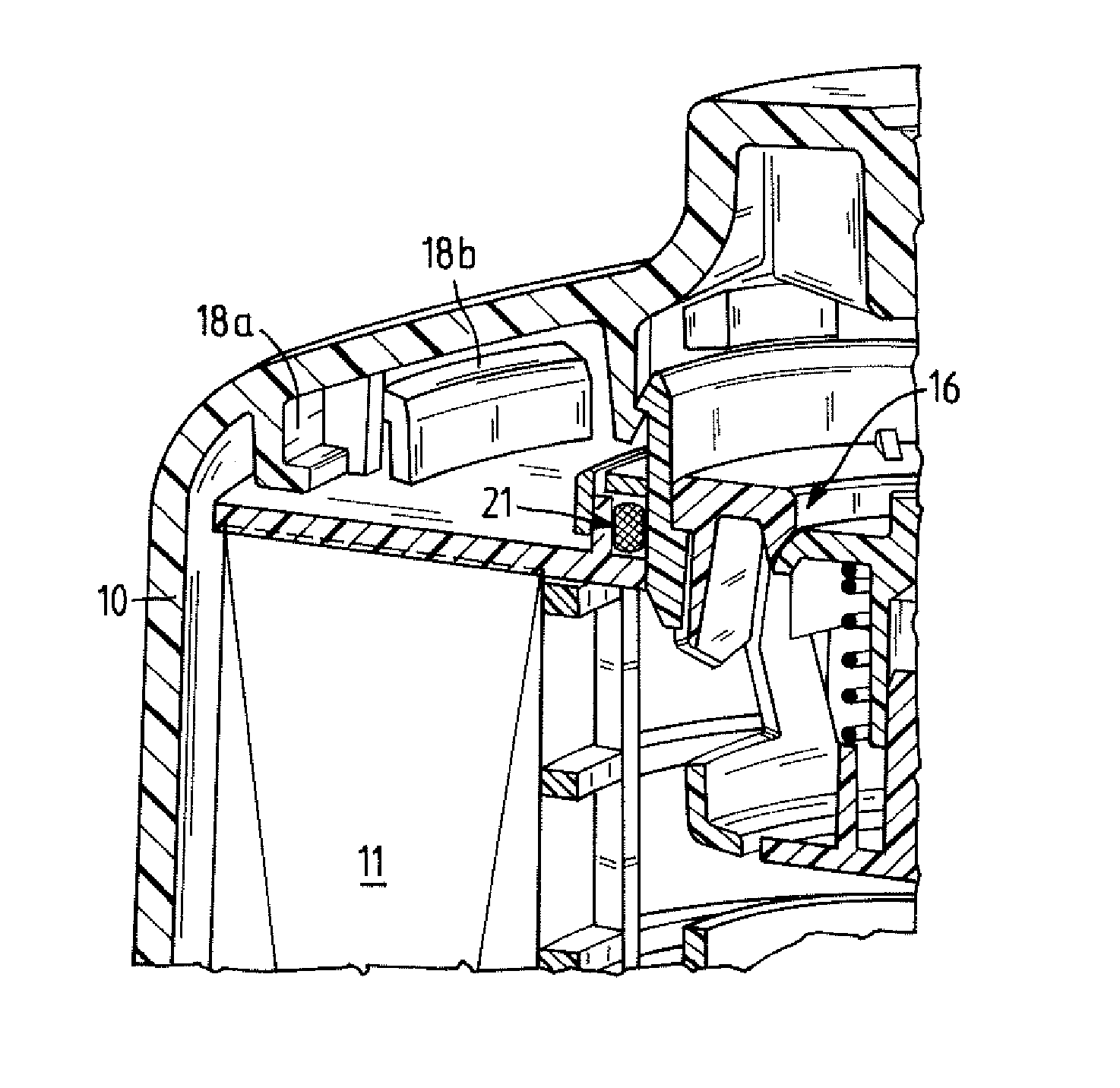
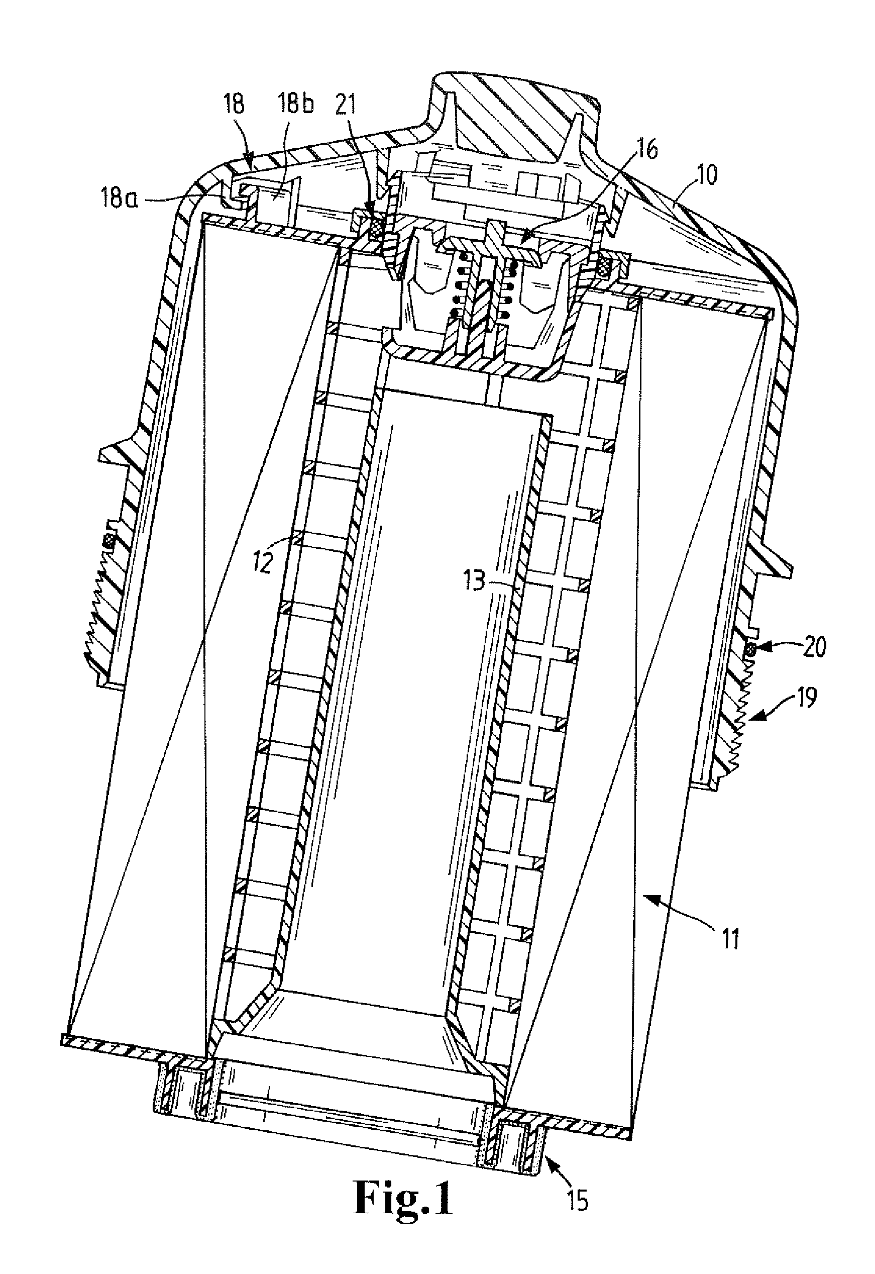
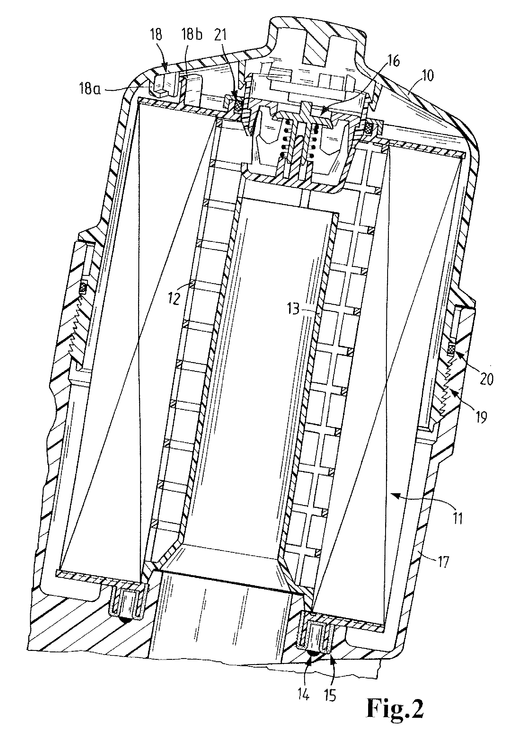
[0014]FIG. 1 illustrates a filter element 11 seated in the filter lid 10 and provided with an integrated support tube 12. However, such a support tube 12 can also be fixedly mounted in the housing. Within the support tube 12 there is a standpipe 13. The standpipe 13 prevents, when removing the filter element 11, mixing of oil of the unfiltered side with oil of the filtered side. The drain passage 14 (see FIG. 2) is separated by a double-concentric seal 15 from the filtered side as well as from the unfiltered side. The double-concentric seal 15 can be produced by a two-component method, for example, by injection molding a combination of hard and soft sealing materials. A filter bypass valve 16 is fixedly snapped into place as a permanent filter part in the filter lid 10 and opens for an opening pressure of approximately 2 bar. Alternatively, such a bypass valve 16 can also be arranged in the filter element 11.

[0015]The filter element 11 is illustrated in FIG. 1 in the position for re...


PUM

PropertyMeasurementUnit
opening pressureaaaaaaaaaa
frictionaaaaaaaaaa
pressureaaaaaaaaaa

Abstract

A liquid filter has a filter housing with a first thread and a drain passage. A filter element including a filter medium is arranged in the filter housing. A filter lid is provided with a second thread configured to engage the first thread for connecting the filter lid to the filter housing. The filter lid further has a filter by pass valve for bypassing the filter element when a pressure loss that is too high occurs when liquid passes through the filter medium of the filter element. First bayonet connectors are provided on the filter lid and second bayonet connectors are provided on the filter element for connecting the filter element to the filter lid by engaging the first bayonet connectors. A double-concentric seal is arranged on the filter element for closing off the drain passage.

Description

TECHNICAL FIELD[0001]The invention relates to a filter, in particular an oil filter or fuel filter for a motor vehicle. The invention further relates to a round filter element comprised of a filter medium for use in the aforementioned filter, in particular oil filter or fuel filter for a motor vehicle.BACKGROUND OF THE INVENTION[0002]In known upright oil filters, the filter element is to be frequently removed together with the filter lid after unscrewing the filter lid. In this connection, the filter element is often attached by detent hooks on the filter lid. Such a filter element that is secured by detent hooks on the filter lid is disclosed, for example, in DE 299 21 168. In this disclosure, the detent hooks of the filter lid must however be decoupled in the mounted operating state from the filter element. If this were not the case, axial movement of the lid would be transmitted onto the filter element thus causing friction and wear at sealing locations of the filter element. Thi...

Claims


Application Information

Patent Timeline
Patent Type & Authority Patents(United States)
IPC IPC(8): B01D27/00B01D35/30
CPCB01D35/147B01D35/153B01D35/16B01D2201/291B01D2201/305B01D2201/34Y10T29/49826B01D2201/4015
Inventor WEINDORF, MARTIN
Owner MANN HUMMEL GMBH
Learn More