Rolling-sliding unit and jointed shaft comprising the same

a technology of joining shaft and rolling shaft, which is applied in the direction of shafts, bearings, yielding couplings, etc., can solve the problems of shortened raceways, shortened raceways, and shortened raceways, which are relatively expensive to produ

Inactive Publication Date: 2012-04-17
SHAFT FORM ENG GMBH +1
View PDF23 Cites 10 Cited by
  • Summary
  • Abstract
  • Description
  • Claims
  • Application Information

AI Technical Summary

Benefits of technology

[0006]Another object of the invention is to provide a rolling-sliding unit and a jointed shaft which are economical to manufacture.
[0020]In a further development of the inventive concept, at least one of the shaft sections and / or a joint connectable thereto can be connected via a plug-in connection to a driving or driven component. It is particularly preferred if the plug-in connection comprises two components which can be inserted into one another and are each provided with corresponding longitudinal teeth, with the components being fixable relative to one another in the axial direction via a locking device, for example, a securing ring. The pre-tension of the rolling-sliding unit within the jointed shaft has the effect that the components of the jointed shaft that can be plugged into one another remain securely connected to one another during operation without any danger of the locking device or similar connection becoming released.

Problems solved by technology

In conventional rolling-sliding units of the aforementioned type, which are often used in jointed shafts, the danger exists that before installation in a vehicle, for example, during transportation, shaking occurs and causes abrupt extension or retraction of the journal relative to the profiled sleeve.
This can lead to damage to the components of the rolling-sliding unit and such damage might not be noticeable until later.
It is herein considered to be disadvantageous that the raceways, which are relatively expensive to produce, are shortened by securing rings or the like.

Method used


Image

  • Rolling-sliding unit and jointed shaft comprising the same
  • Rolling-sliding unit and jointed shaft comprising the same

Examples


Embodiment Construction

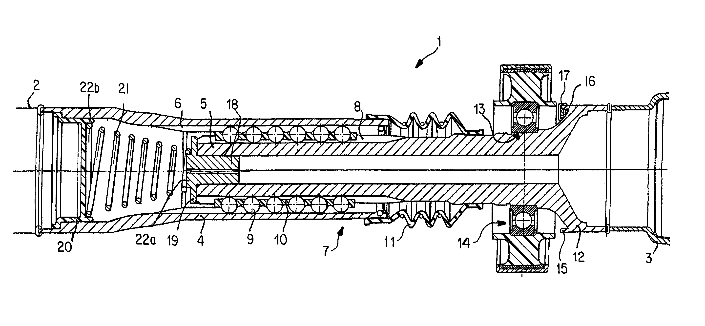
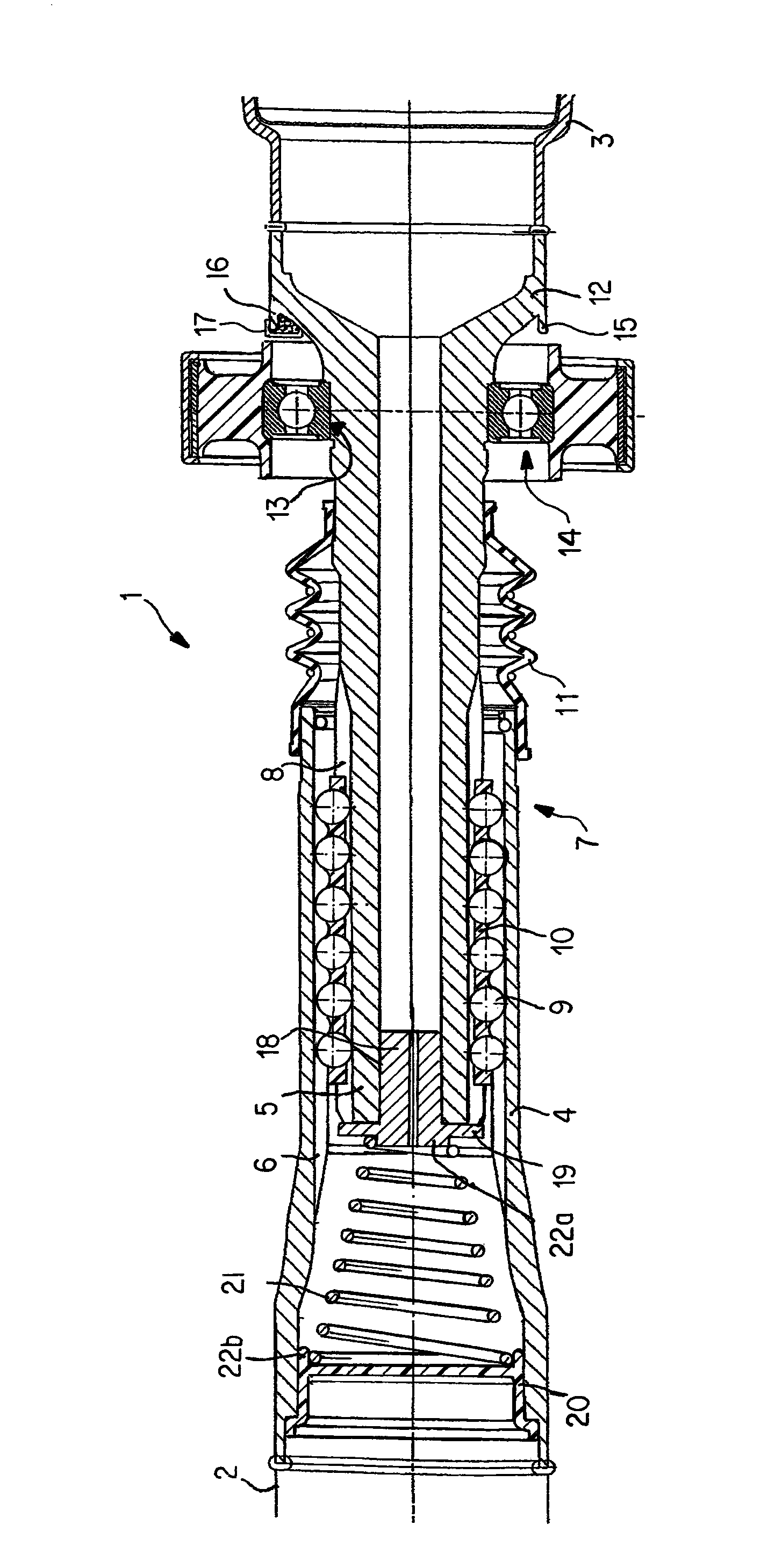
[0023]The section of a jointed shaft 1 shown in the FIGURE comprises a first shaft section which is constructed from a tubular shaft 2 and a second shaft section (not shown in the FIGURE), wherein the two shaft sections are connected to one another in rotationally secured manner via a central joint. In the FIGURE, only one section of the external drive hub 3 of the central joint is shown.

[0024]In the embodiment shown, the tubular shaft 2 is welded to a profiled sleeve 4, which is a component of a rolling-sliding unit. Accommodated displaceably in the profiled sleeve 4 is a journal 5, which is welded to the external driving hub 3 of the central joint. Outer raceways 6 are provided at certain sites on the internal surface of the profiled sleeve 4, while inner raceways 8 are provided in a displacement region 7 of the journal 5.

[0025]The outer raceways 6 and the inner raceways 8 extend parallel to one another and are associated with one another in pairs. Accommodated in each pair made u...


PUM


Abstract

A rolling-sliding unit, particularly for a jointed shaft, including a profiled sleeve (4) having outer raceways on an interior surface thereof; a journal (5) which is displaceable in the profiled sleeve (4) and which has inner raceways on an exterior surface thereof, and balls (9) in the raceways between the profiled sleeve and the journal for transmitting torque. A cover is provided on the journal of the rolling-sliding unit and an elastic element is arranged between the profiled sleeve and the journal of the rolling-sliding unit. A jointed shaft comprising a rolling-sliding unit of the described type also is described.

Description

CROSS REFERENCE TO RELATED APPLICATIONS[0001]This application is a continuation of international patent application no. PCT / DE2008 / 001107, filed Jul. 2, 2008, designating the United States of America and published in German on Jan. 29, 2009 as WO 2009,012746, the entire disclosure of which is incorporated herein by reference. Priority is claimed based on Federal Republic of Germany patent application no. DE 10 2007 035 468.3, filed Jul. 26, 2007.BACKGROUND OF THE INVENTION[0002]The invention relates to a rolling-sliding unit comprising a profiled sleeve, on the internal surface of which outer raceways are provided at least at certain sites, and having a journal which is movable in the axial direction in said profiled sleeve, on the external surface of which inner raceways are provided at least at certain sites, and having balls which, for torque transmission, are arranged in mutually assigned paired outer raceways and inner raceways. The invention also relates to a jointed shaft wit...

Claims


Application Information

Patent Timeline
Patent Type & Authority Patents(United States)
IPC IPC(8): F16C3/03F16D3/06
CPCF16C3/035F16D3/065F16C2326/06
Inventor DISSER, CLAUS
Owner SHAFT FORM ENG GMBH
Why Eureka
Try Eureka