Control circuit for inverter

a control circuit and inverter technology, applied in the field of inverters, can solve the problems of high relative precision and difficulty in generating dimming reference voltages, and achieve the effect of high precision

Inactive Publication Date: 2012-04-17
ROHM CO LTD
View PDF11 Cites 2 Cited by
  • Summary
  • Abstract
  • Description
  • Claims
  • Application Information

AI Technical Summary

Benefits of technology

[0013]With such an embodiment, the composite current obtained by combining the multiple first duplicated currents is adjusted in a discrete manner according to the mirror ratio. Accordingly, the voltage drop that occurs at the converting resistor is also controlled in a discrete manner. The mirror ratio of a current mirror circuit exhibits small relative irregularity. Thus, such an arrangement provides increased relative precision of the reference voltage, thereby allowing the dimming operation to be performed with high precision.
[0015]With such an arrangement, the resistance values of the first resistor and the second resistor change in association with each other. Accordingly, even if the resistance of the first resistor changes, leading to a change in the composite current obtained by combining the first duplicated currents, the resistance of the second resistor changes such that the change in composite current is canceled out. Thus, such an arrangement suppresses the absolute value of irregularity in each current, in addition to suppressing relative irregularity among these currents.
[0022]Such an arrangement allows the ratio of the change in luminance with respect to the base luminance to be changed according to the resistance of the second resistor.
[0024]Such an embodiment allows the relative luminance of a fluorescent lamp to be adjusted with high precision.

Problems solved by technology

In a case in which such multiple dimming reference voltages are generated at a circuit external to a control circuit as in conventional arrangements, it is difficult to generate the dimming reference voltages with high relative precision.

Method used


Image

  • Control circuit for inverter
  • Control circuit for inverter
  • Control circuit for inverter

Examples


Embodiment Construction

[0033]Description will be made below regarding preferred embodiments according to the present invention with reference to the drawings. The same or similar components, members, and processes are denoted by the same reference numerals, and redundant description thereof will be omitted as appropriate. The embodiments have been described for exemplary purposes only, and are by no means intended to restrict the present invention. Also, it is not necessarily essential for the present invention that all the features or a combination thereof be provided as described in the embodiments.

[0034]In the present specification, the state represented by the phrase “the member A is connected to the member B” includes a state in which the member A is indirectly connected to the member B via another member that does not affect the electric connection therebetween, in addition to a state in which the member A is physically and directly connected to the member B.

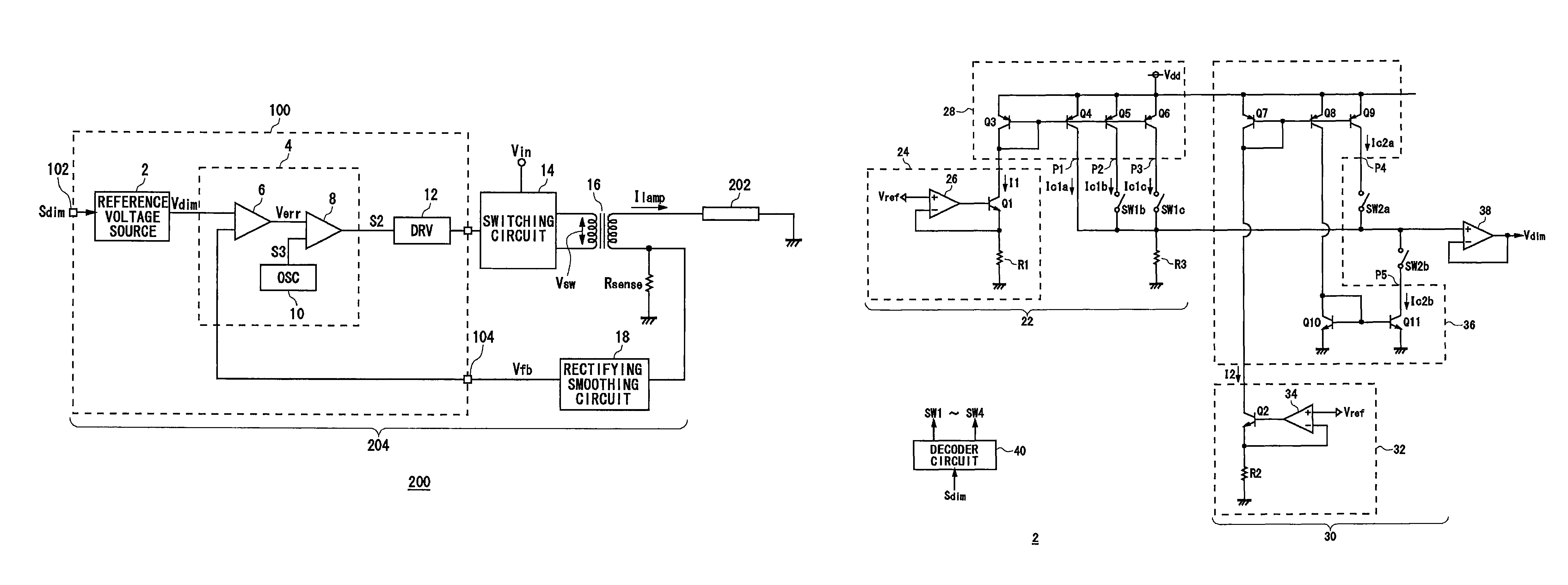
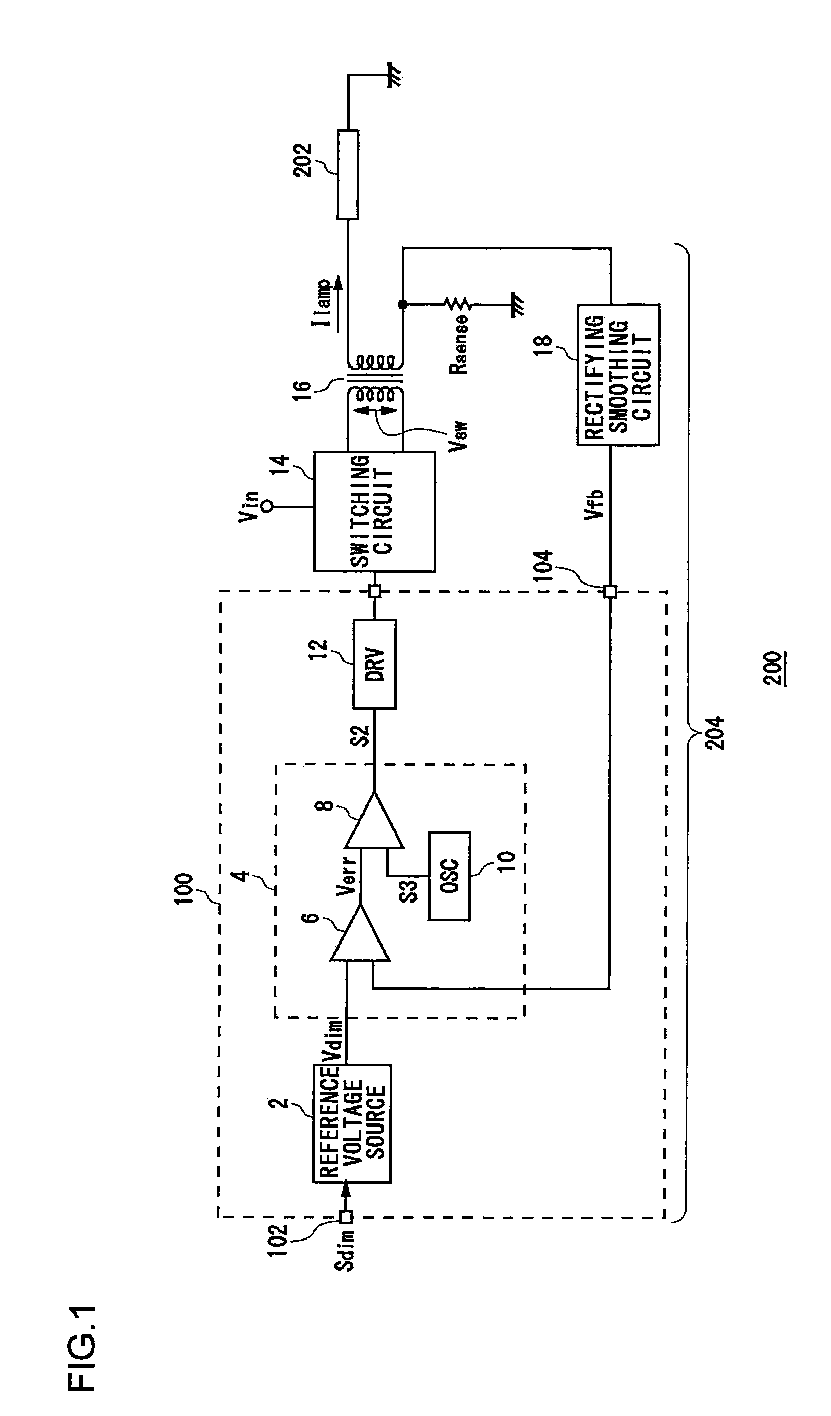
[0035]FIG. 1 is a circuit diagram which s...


PUM


Abstract

A reference voltage source generates a reference voltage for adjusting an electric current for a dimming operation. The first current source generates a first current. A first current mirror circuit includes multiple output terminals, duplicates the first current, and outputs multiple first duplicated currents via the multiple output terminals. Multiple first switches are provided on paths for the respective multiple first duplicated currents. A converting resistor, with one terminal set to a fixed electric potential, is provided on a path for the multiple first duplicated currents output from the first current mirror circuit. A decoder circuit receives a control signal from an external circuit, and controls the ON / OFF operations of the multiple first switches. The reference voltage source outputs, as the reference voltage, a voltage that corresponds to a voltage drop that occurs at a converting resistor.

Description

[0001]This is a U.S. national stage application of International Application No. PCT / JP2008 / 001792, filed on 4 Jul. 2008. Priority under 35 U.S.C. §119(a) and 35 U.S.C. §365(b) is claimed from Japanese Application No. JP2007-186794, filed 18 Jul. 2007, the disclosure of which is also incorporated herein by reference.BACKGROUND OF THE INVENTION[0002]1. Field of the Invention[0003]The present invention relates to an inverter which supplies driving voltage to a fluorescent lamp or the like, and particularly to a dimming control technique for adjusting the luminance of a fluorescent lamp.[0004]2. Description of the Related Art[0005]In recent years, liquid crystal display TVs, which provide a TV having a thin shape and a large size, are becoming popular as replacements for CRT-based TVs. Liquid crystal display TVs include multiple cold cathode fluorescent lamps (which will be referred to as “CCFLs” hereafter) or external electrode fluorescent lamps (which will be referred to as “EEFLs” h...

Claims


Application Information

Patent Timeline
Patent Type & Authority Patents(United States)
IPC IPC(8): G05F1/00
CPCH05B41/2822H05B41/3921Y10S315/04H05B41/24H05B41/392
Inventor IMANAKA, YOSHINORI
Owner ROHM CO LTD
Why Eureka
Try Eureka