Check patentability & draft patents in minutes with Patsnap Eureka AI!

Motor driving device

a technology of motor driving and driving coil, which is applied in the direction of electric programme control, dynamo-electric converter control, instruments, etc., can solve the problems of inability to detect avalanche state, false detection of coil disconnection, and poor coil coupling between the coils lb>1/b> and lb>2/b>,

Active Publication Date: 2012-04-17
SEMICON COMPONENTS IND LLC
View PDF8 Cites 1 Cited by
  • Summary
  • Abstract
  • Description
  • Claims
  • Application Information

AI Technical Summary

Benefits of technology

Prevents false detection of coil disconnection and thermal destruction by accurately identifying negative currents, ensuring the switching elements are kept off when necessary, thus maintaining device integrity across various motor specifications.

Problems solved by technology

For example, if a hybrid motor and a PM (Permanent Magnet) motor are compared, coupling between the coils L1 and L2 and the coils L3 and L4 might become poorer in the PM motor due to variations in product characteristics.
Therefore, in such a PM motor, in the case where detection of the avalanche current is executed, before the switching element is turned off and the current is fully decreased, there might be false detection of coil disconnection.
However, if the detection timing of the avalanche current is delayed, the avalanche state cannot be detected in the case of the hybrid motor with a relatively short time period of the avalanche state when the coil is disconnected.

Method used


Image

  • Motor driving device
  • Motor driving device
  • Motor driving device

Examples


Embodiment Construction

[0030]At least the following details will become apparent from descriptions of this specification and of the accompanying drawings.

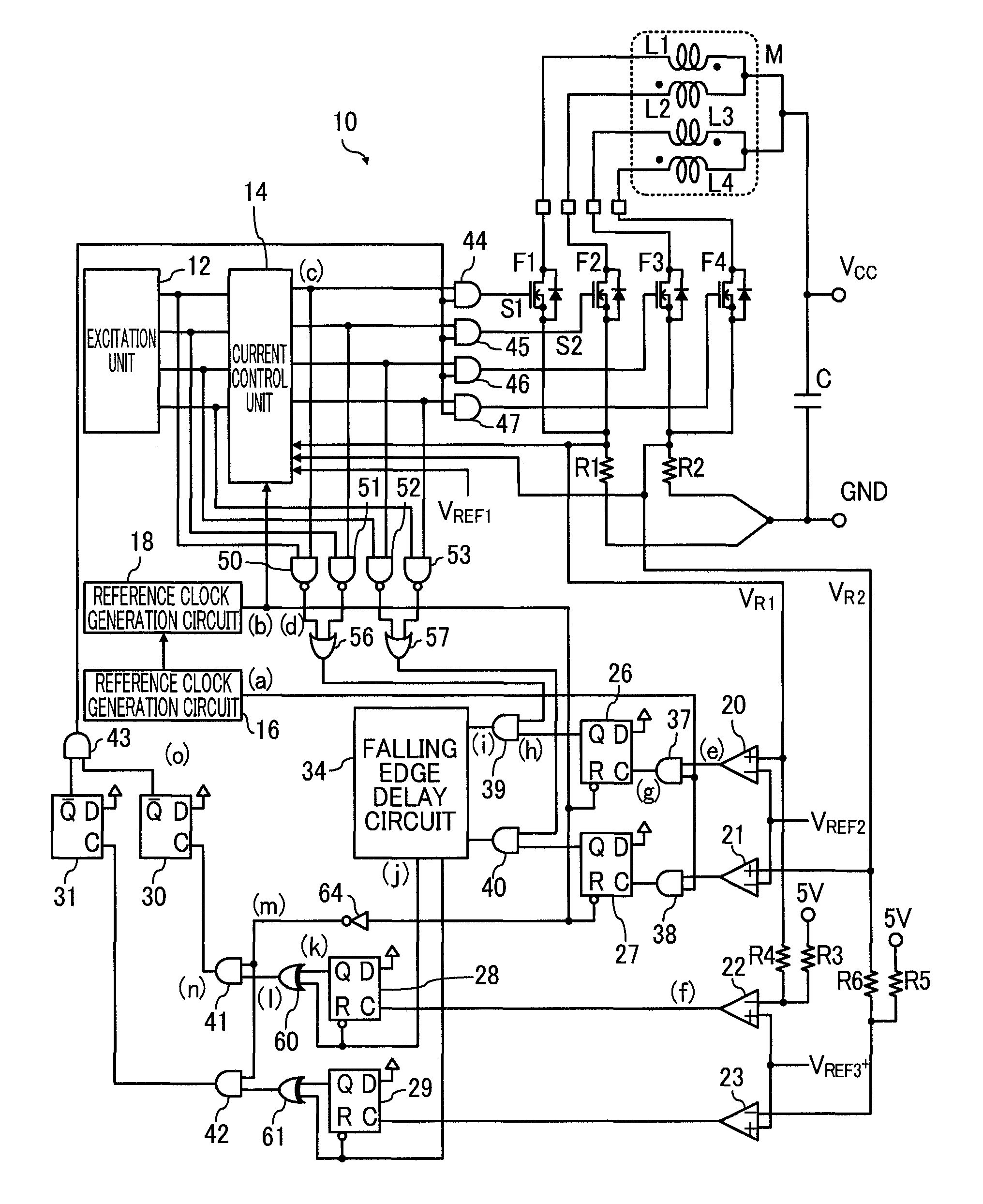
[0031]FIG. 1 is a diagram illustrating a configuration of a motor driving device according to an embodiment of the present invention. A motor driving device 10 is integrated and drives a motor M connected through a connecting terminal.

[0032]The motor M is a two-phase unipolar stepping motor including coils L1 to L4. The coils L1 and L2 are wound around the same stator in directions opposite to each other and electromagnetically coupled, to create an A-phase magnetic field. Similarly, the coils L3 and L4 are wound around the same stator in directions opposite to each other and electromagnetically coupled, to create a B-phase magnetic field. In the coils L1 to L4, a power voltage VCC of 24V is applied to each one end thereof, and the other ends thereof is connected to switching elements F1 to F4 through connecting terminals, respectively, for example.

[0033...


PUM


Abstract

A motor-driving device comprising: a switching element to control a current passed through a first coil of a stepping motor including the first and a second coils electromagnetically coupled; a rectifier element to be energized in a ground-side-to-second-coil direction; a coil-current-detection unit to detect a current passed through the first coil; a regeneration-current-detection unit to detect a current passed through the rectifier element; a control unit to turn off the switching element when the current passed through the first coil reaches a predetermined-set current based on a detection result of the coil-current-detection unit; and a negative-current-detection unit to detect whether a negative current greater in absolute value than a predetermined-set value is passed through the rectifier element based on a detection result of the regeneration-current-detection unit, the control unit keeping the switching element off when the negative current is not passed, based on a detection result of the negative-current-detection unit.

Description

CROSS-REFERENCE TO RELATED APPLICATION[0001]This is a continuation application which claims the benefit of priority to International Patent Application No. PCT / JP2008 / 52344, filed Feb. 13, 2008. The full contents of the International Patent Application are incorporated herein by reference.BACKGROUND OF THE INVENTION[0002]1. Field of the Invention[0003]The present invention relates to a motor driving device.[0004]2. Description of the Related Art[0005]A stepping motor is used for controlling various electronic devices in positioning of a carriage in a printer or the like. FIG. 6 is a diagram illustrating an example of a common motor driving device for driving a two-phase stepping motor. A motor M includes coils L1 and L2 creating an A-phase magnetic field and coils L3 and L4 creating a B-phase magnetic field, and a motor driving device 100 is provided in order to control driving of the motor M. The motor driving device 100 is configured with switching elements F1 to F4 for controllin...

Claims


Application Information

Patent Timeline
Patent Type & Authority Patents(United States)
IPC IPC(8): G05B19/40
CPCB41J19/202H02P8/12H02P8/36
Inventor ARAI, MITSUJIOIKE, TAKESHI
Owner SEMICON COMPONENTS IND LLC
Features
  • R&D
  • Intellectual Property
  • Life Sciences
  • Materials
  • Tech Scout
  • Unparalleled Data Quality
  • Higher Quality Content
  • 60% Fewer Hallucinations
Learn More