Vibration sensitive ablation device and method

a vibration-sensitive, ablation device technology, applied in the field of ablation devices, can solve the problems of non-conductive lesion, blocked electrical pathways within the tissue, and insufficient function of electrical signals

Inactive Publication Date: 2012-04-24
MEDTRONIC INC
View PDF377 Cites 939 Cited by
  • Summary
  • Abstract
  • Description
  • Claims
  • Application Information

AI Technical Summary

Problems solved by technology

Occasionally, these electrical signals do not function properly.
The scar tissue resulting from the procedure results in a non-conductive lesion.
Lower levels of energy are used to cause cell damage but leave the structure intact so that electrical pathways are blocked within the tissue.
This technique is time-consuming (which is not good for the patient) and requires multiple accurate placements of the electrode (which may be difficult for the physician).
In addition, it may be difficult to obtain adequate tissue contact pressure for each electrode in a multi-electrode ablation device.
However, due to the unique chemical structure of the water molecule, additional heat is required for water to change phase from the liquid to gaseous phase.
If the temperature at the ablation site exceeds 100° C., the water will change phase, boil and may result in an audible “steam pop” within the tissue.
This pop may damage and even rupture the tissue.
Irrigation cooling of the site shifts the location of the “steam pop” even deeper within the tissue, resulting in even greater damage than a superficial pop.
However, due to such reasons as slow human reaction, vibration damping from the device or vibration damping from the tissue, the user is often not able to halt or modify ablation in time to prevent damage.

Method used


Image

  • Vibration sensitive ablation device and method
  • Vibration sensitive ablation device and method
  • Vibration sensitive ablation device and method

Examples


Embodiment Construction

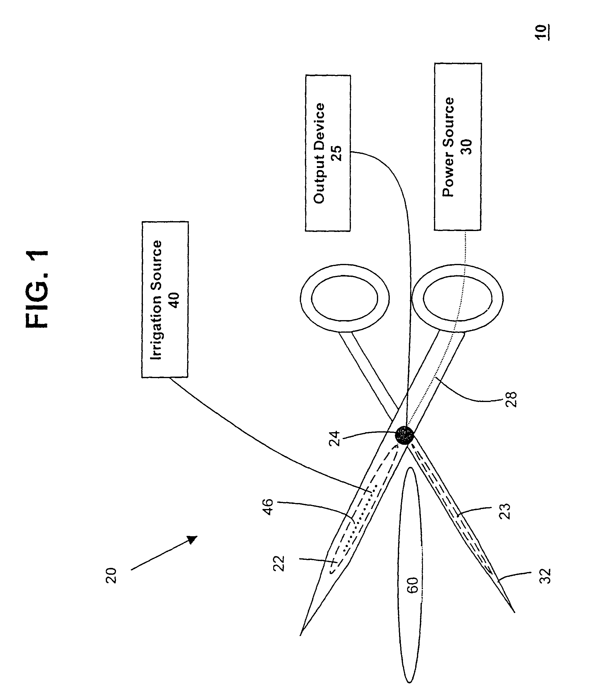
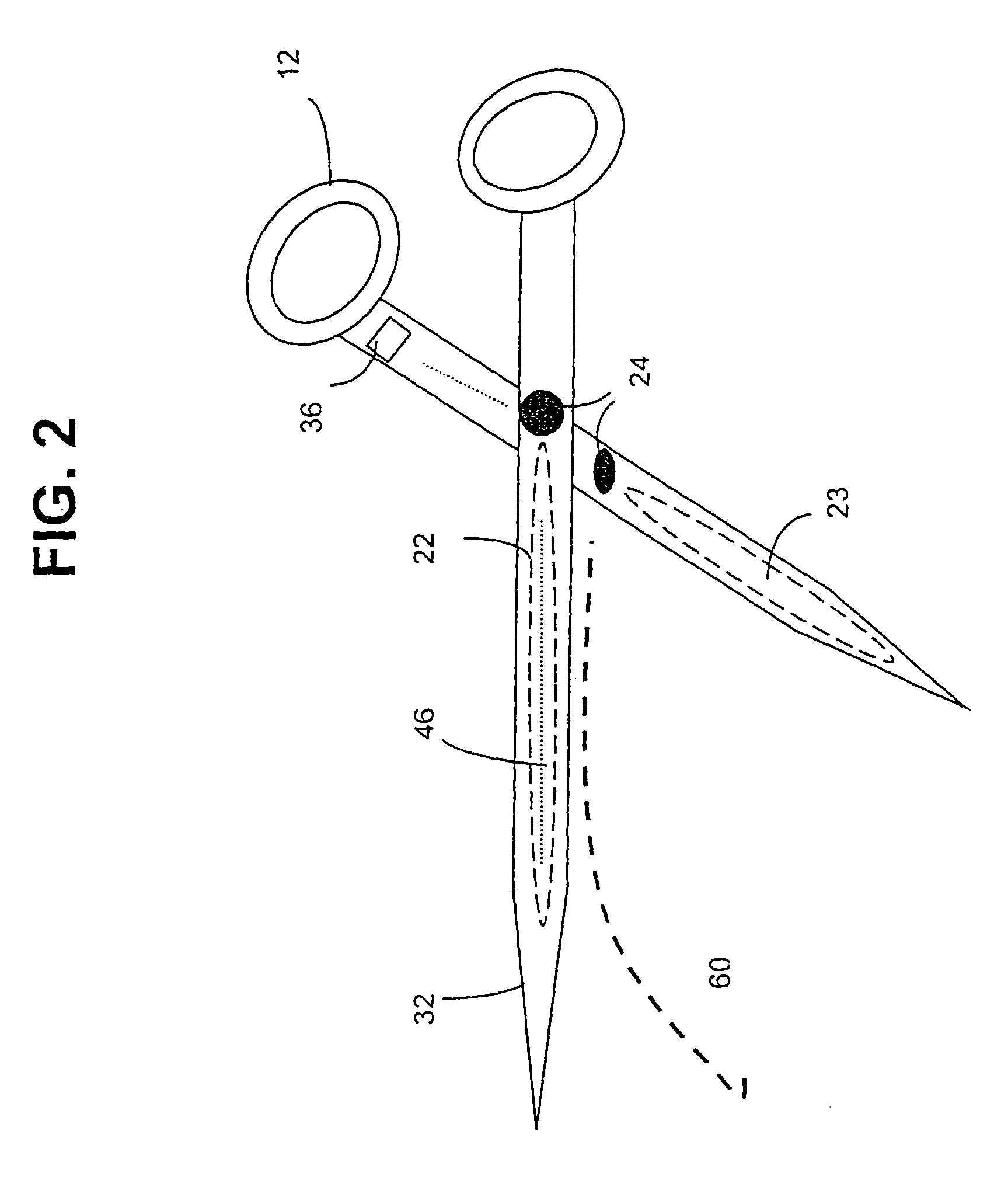
[0025]FIG. 1 shows a system 10 for ablating tissue in accordance with the present invention. Typically the tissue to be ablated may be located within the body cavity, such as the endocardial or epicardial tissue of the heart. Other body organ tissue, such as the liver or lung, may also be ablated using the present invention. System 10 may include an ablation apparatus 20 that comprises a conductive electrode 22, a sensor 24 connected to an output device 25 and a connection 28 to a source of ablation energy. System 10 may further include a power source 30 that provides ablation energy. System 10 may also include an indifferent (non-ablating) electrode 23 which may serve as the return plate for energy transmitted through electrode 22. Electrode 23 may be placed elsewhere on the patient's body than the ablation site. For example, electrode 23 may be placed on the patient's back or thigh. System 10 may further include an irrigation source 40 that provides irrigation fluid to the ablatio...


PUM

PropertyMeasurementUnit
temperatureaaaaaaaaaa
pressureaaaaaaaaaa

Abstract

An ablation apparatus including a maneuvering mechanism, a conductive element attached to the apparatus, a sensor attached to the apparatus and an output device in communication with the sensor is provided. The sensor senses vibration during the ablation procedure and sends a signal to the output device to reduce power to the conductive element.

Description

CROSS-REFERENCE TO RELATED APPLICATION[0001]This application is a continuation of U.S. patent application Ser. No. 09 / 844,221, filed Apr. 26, 2001, now abandoned, which is a continuation-in-part of U.S. patent application Ser. No. 09 / 559,604, filed Apr. 27, 2000, now abandoned.FIELD OF THE INVENTION[0002]This invention relates to ablation devices that are used to create lesions in tissue. More particularly, this invention relates to ablation devices that are capable of monitoring the level of energy being used to ablate the tissue and of preventing the energy from creating tissue-damaging events such as a “steam pop.”BACKGROUND OF THE INVENTION[0003]The action of the heart is known to depend on electrical signals within the heart tissue. Occasionally, these electrical signals do not function properly. The maze procedure is a surgical operation for patients with atrial fibrillation that is resistant to medical treatment. In this procedure, incisions are created in the right and left ...

Claims


Application Information

Patent Timeline
Patent Type & Authority Patents(United States)
IPC IPC(8): A61B18/18A61B17/00A61B17/02A61B17/30A61B18/14
CPCA61B18/1442A61B18/1445A61B18/14A61B2218/002A61B2017/00022A61B2017/00084A61B2017/00115A61B2017/00128A61B2017/00243A61B2017/00247A61B2017/003A61B2017/0243A61B2017/306A61B2018/00011A61B2018/00107A61B2018/0016A61B2018/00291A61B2018/00351A61B2018/00392A61B2018/00577A61B2018/00666A61B2018/00672A61B2018/00702A61B2018/00708A61B2018/00791A61B2018/00797A61B2018/00815A61B2018/00821A61B2018/0088A61B2018/1253A61B2018/126A61B2018/146A61B2018/1472A61B18/1402
Inventor FRANCISCHELLI, DAVID E.JAHNS, SCOTT E.KEOGH, JAMES R.
Owner MEDTRONIC INC
Why Eureka
Try Eureka