Multiple-stage granular moving bed apparatus

a moving bed and multi-stage technology, applied in the direction of machines/engines, separation with moving sorbents, drying machines, etc., can solve the problems of affecting the environment, affecting the purification efficiency of particles smaller than 10 microns, and affecting the removal efficiency of particles, so as to achieve satisfactory purification efficiency and occupie less space.

Active Publication Date: 2012-04-24
INST NUCLEAR ENERGY RES ROCAEC
View PDF11 Cites 3 Cited by
  • Summary
  • Abstract
  • Description
  • Claims
  • Application Information

AI Technical Summary

Benefits of technology

[0010]The present invention provides a multiple-stage granular moving-bed apparatus, which utilizes a plurality of serially connected integrated moving-bed units for cleaning up a raw gas flow. As the raw gas is directed to flow from the bottommost integrated moving-bed unit to the topmost one in the apparatus and passing through each and every integrated moving-bed units between the two in sequence, the raw gas is purified in a multiple-stage filtering process enabled by the multiple-stage granular moving-bed apparatus with satisfactory purification efficiency while occupied less space comparing with conventional moving-bed apparatuses.
[0011]The present invention provides a multiple-stage granular moving-bed apparatus, which not only is capable of utilizing a plurality of serially connected integrated moving-bed units for cleaning up a raw gas flow, but also is capable of utilizing a regeneration unit for regenerating and recycling a granular material used in the apparatus so as to maintain the gas-purification ability of the granular material and thus prolong the operational lifespan of the multiple-stage granular moving-bed apparatus.

Problems solved by technology

Coal-fired power plants, or incineration plants generate high-temperature gas containing a large amount of fly ashes and dusts, sulfides, nitrides or other contaminants, and if the exhaust flue gas or raw syn-gas is emitted without processing, the environment of mankind will be affected seriously.
Their removal efficiency is, however, limited to about 90% and rapidly deteriorates for particles smaller than 10 microns.
A disadvantage when compared with electrostatic dust precipitators is the larger pressure drop and relatively low gas face velocity.
Low gas face velocity gives rise to large filtration surface and inherently high costs.
Typical problems encountered during the testing are the breakage and strength degradation of ceramic candles owing to the overheating, thermal shocks and excessive pressure drop.
In addition, the plenum vibration and back-pulse cleaning expose the candle filters to thermal and mechanical fatigue stresses that may ultimately lead to fracture of the filter elements.
The principal disadvantage of these filters is that either a very thick bed or very fine granular material (or both) are required to give high removal efficiency of particulates in the 0.5 to 10 microns size range.
The requirement for thick beds results in large expensive equipment, while the use of very fine granular material causes high pressure drop, poor bed flow characteristics, accompanied by stagnant zones and hot spots in granular moving bed, causing corrosion and plaques on louver wall.

Method used


Image

  • Multiple-stage granular moving bed apparatus
  • Multiple-stage granular moving bed apparatus
  • Multiple-stage granular moving bed apparatus

Examples


first embodiment

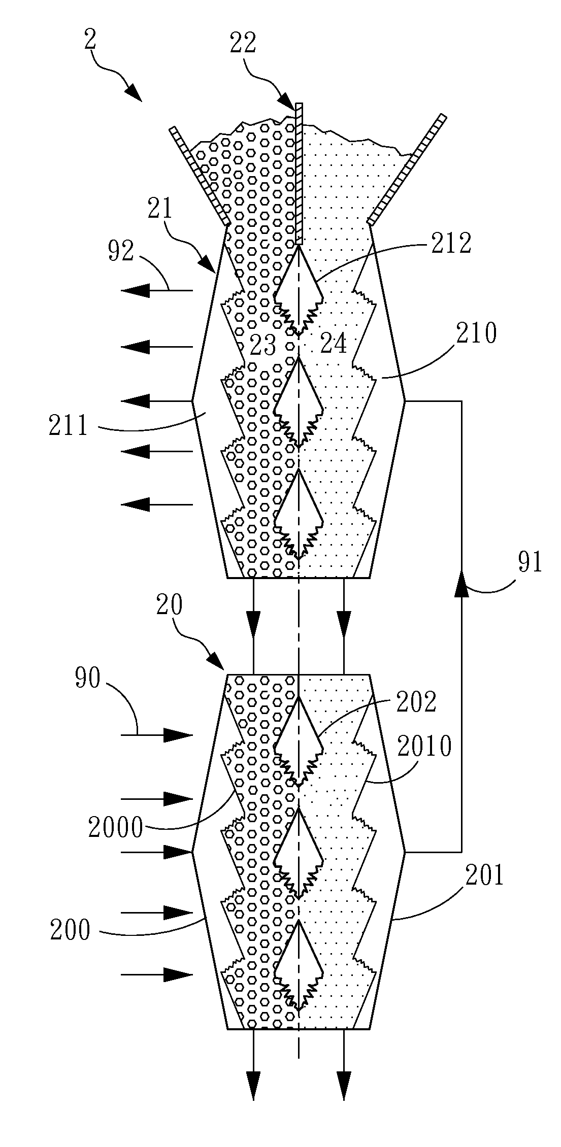
[0027]Please refer to FIG. 3A, which is a schematic view of a multiple-stage granular moving-bed apparatus according to the invention. In this exemplary embodiment, the multiple-stage granular moving-bed apparatus 2 comprises: a first integrated moving-bed unit 20 and a second integrated moving-bed unit 21. The first integrated moving-bed unit 20 has an inlet part 200, an outlet part 201 and a plurality of flow-corrective elements 202, in which the inlet part 200 is configured with a first wall 2000 with a plurality of louvers, and the outlet part 201 is located at a side of the inlet part 200 and is configured with a second wall 2010 with a plurality of louvers disposed correspondingly to the first wall 2000 in respective. As for the plural flow-corrective elements 202, they are all being disposed between the inlet part 200 and the outlet part 201 for defining two channels in the first integrated moving-bed unit 20, each channel for individual stage of technological process. There ...

third embodiment

[0033]Please refer to FIG. 3C, which is a schematic view of a multiple-stage granular moving-bed apparatus according to the invention. The difference between this embodiment and the prior two embodiments is that: there is an additional integrated moving-bed unit, referring as the third integrated moving-bed unit 25, being configured in the multiple-stage granular moving-bed apparatus at a position between the first and the second integrated moving-bed units 20, 21. Similarly, the multiple-stage granular moving-bed apparatus shown in FIG. 3D is the one with the additional third integrated moving-bed unit 25, but is different from the one shown in FIG. 3C in that: the apparatus of FIG. 3D is designed with alternating channels as the one shown in FIG. 3B. Thus, each of the multiple-stage granular moving-bed apparatus shown in FIG. 3C and FIG. 3D is actually a six-stage granular moving-bed apparatus. Operationally, the raw gas 90 is guided to flow from the bottommost first integrated mo...

fourth embodiment

[0037]Please refer to FIG. 6A, which is a schematic view of a multiple-stage granular moving-bed apparatus according to the invention. The multiple-stage granular moving-bed apparatus shown in FIG. 6A is basically similar to those shown in previous embodiments, but is different in that: the multiple-stage granular moving-bed apparatus in FIG. 6A is further configured with a regeneration unit for regenerating and recycling those granular materials flowing in channels defined in the multiple-stage granular moving-bed apparatus. In this embodiment, the multiple-stage granular moving-bed apparatus comprises two regenerators 26, 27, which are designed for regenerating and recycling granular materials that are comparatively more expensive. However, for those granular materials that are not expensive, the regeneration unit is not a necessity for the multiple-stage granular moving-bed apparatus. As for the granular materials used in this embodiment, the granular material 23 can be the FM-A ...


PUM

PropertyMeasurementUnit
sizeaaaaaaaaaa
shapeaaaaaaaaaa
temperatureaaaaaaaaaa

Abstract

A multiple-stage granular moving-bed apparatus comprises a first integrated moving-bed unit, a second integrated moving-bed unit and at least one granular material. The first integrated moving-bed unit, having a first inlet part for providing a raw gas flowing therein, a first outlet part for providing a partially-cleaned gas flowing thereout, and a plurality of first flow-corrective elements disposed therebetween for defining two channels. The second integrated moving-bed unit, coupled to the first integrated moving-bed unit, having a second inlet part for providing the partially-cleaned gas flowing therein, a second outlet part for providing a completely-cleaned gas flowing thereout, and a plurality of second flow-corrective elements disposed therebetween for defining two channels. The at least one granular material flows through the two channels respectively and then passes through the two channels respectively.

Description

FIELD OF THE INVENTION[0001]The present invention relates to a granular moving-bed apparatus, and more particularly to a multiple-stage granular moving-bed filter capable of cleaning up a raw gas by forcing it to pass sequentially through a plurality of filtering units.BACKGROUND OF THE INVENTION[0002]Coal-fired power plants, or incineration plants generate high-temperature gas containing a large amount of fly ashes and dusts, sulfides, nitrides or other contaminants, and if the exhaust flue gas or raw syn-gas is emitted without processing, the environment of mankind will be affected seriously. In order to solve the environmental pollution problems due to hazardous gases, industrial countries have to constitute strict emission standards, and also input considerable research and development (R&D) resources to investigate how to remove the harmful pollutants in the gas streams effectively so as to conform to the emission standards.[0003]In prior art, many methods of gas cleanup exist,...

Claims


Application Information

Patent Timeline
Patent Type & Authority Patents(United States)
IPC IPC(8): B01D50/00B01J8/08
CPCB01D46/002B01D46/0036B01D46/38B01D53/06B01D53/0446B01D2253/102B01D2253/106B01D2257/2045B01D2257/404B01D2257/406B01D2259/40083B01D46/58
Inventor CHYOU, YAU-PINSMID, JIRIHSIAU, SHU-SAN
Owner INST NUCLEAR ENERGY RES ROCAEC
Why Eureka
Try Eureka