
Surface light emitting apparatus emitting laser light

a laser light and light-emitting technology, applied in the direction of lighting and heating apparatus, instruments, transportation and packaging, etc., can solve the problems of limiting the application of laser light to small angles, difficult scaling up, and dramatic drop in efficiency and uniformity, so as to achieve good design, control more or less accurately, and good manufacturing

Inactive Publication Date: 2012-05-01
GK BRIDGE 1
View PDF22 Cites 0 Cited by
  • Summary
  • Abstract
  • Description
  • Claims
  • Application Information

AI Technical Summary

Benefits of technology

[0011]Therefore, it is an object of the present invention to provide a surface light emitting apparatus capable of providing uniform illumination while efficiently using a laser light.
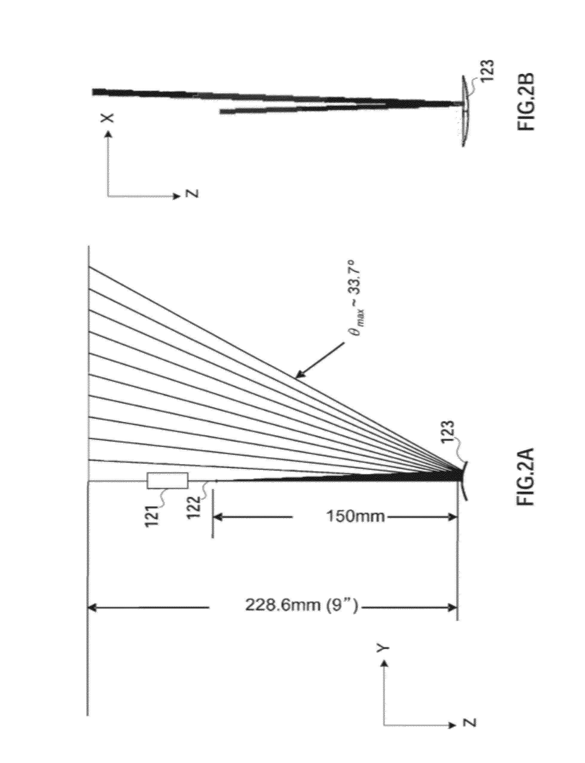
[0013]We propose the use of incoherent beam shaping, i.e., shaping through diffractive optics elements (DOE). Diffractive optics can split a collimated laser beam into many beams (diffractive orders) at determined angles. The new beams bear the same properties as the initial beam, with the power in each beam depending on the diffraction efficiency in each order which can be controlled more or less accurately with a good design and good fabrication. If all diffracted beams have the same power, they can form a uniform line of dots (i.e., a line of light) on a target plane. It is possible to obtain a good uniformity and efficiency with DOEs providing that the maximum diffractive order (or equivalently, the maximum angle of diffracted beam) is small. However, efficiency and uniformity drop dramatically when higher diffractive orders are required (larger angles of diffraction), as it would be to form a long line for a large display. The reason for this is that performing DOE designs use the small angle approximation theory (scalar theory), which limits its application to small angles. (See “Diffractive Optics: Design, Fabrication, and Test” by D. C. O'Shea et al, SPIE Tutorial Texts, Vol. TT62, SPIE Press, 2004). The consequence is that, with DOE alone, this solution is difficult to scale up. Here we propose an integrated method using high efficiency-, high uniformity-DOEs which is applicable to all sizes of displays, without degrading neither the efficiency nor the uniformity of the system. This solution also provides a way to eliminate speckles, which are the grainy texture inherent to laser a light and are undesirable for displays.

Problems solved by technology

However, efficiency and uniformity drop dramatically when higher diffractive orders are required (larger angles of diffraction), as it would be to form a long line for a large display.
The reason for this is that performing DOE designs use the small angle approximation theory (scalar theory), which limits its application to small angles.
The consequence is that, with DOE alone, this solution is difficult to scale up.

Method used


Image

  • Surface light emitting apparatus emitting laser light
  • Surface light emitting apparatus emitting laser light
  • Surface light emitting apparatus emitting laser light

Examples


Embodiment Construction

[0039]An embodiment of the present invention will be described below with reference to the drawings.

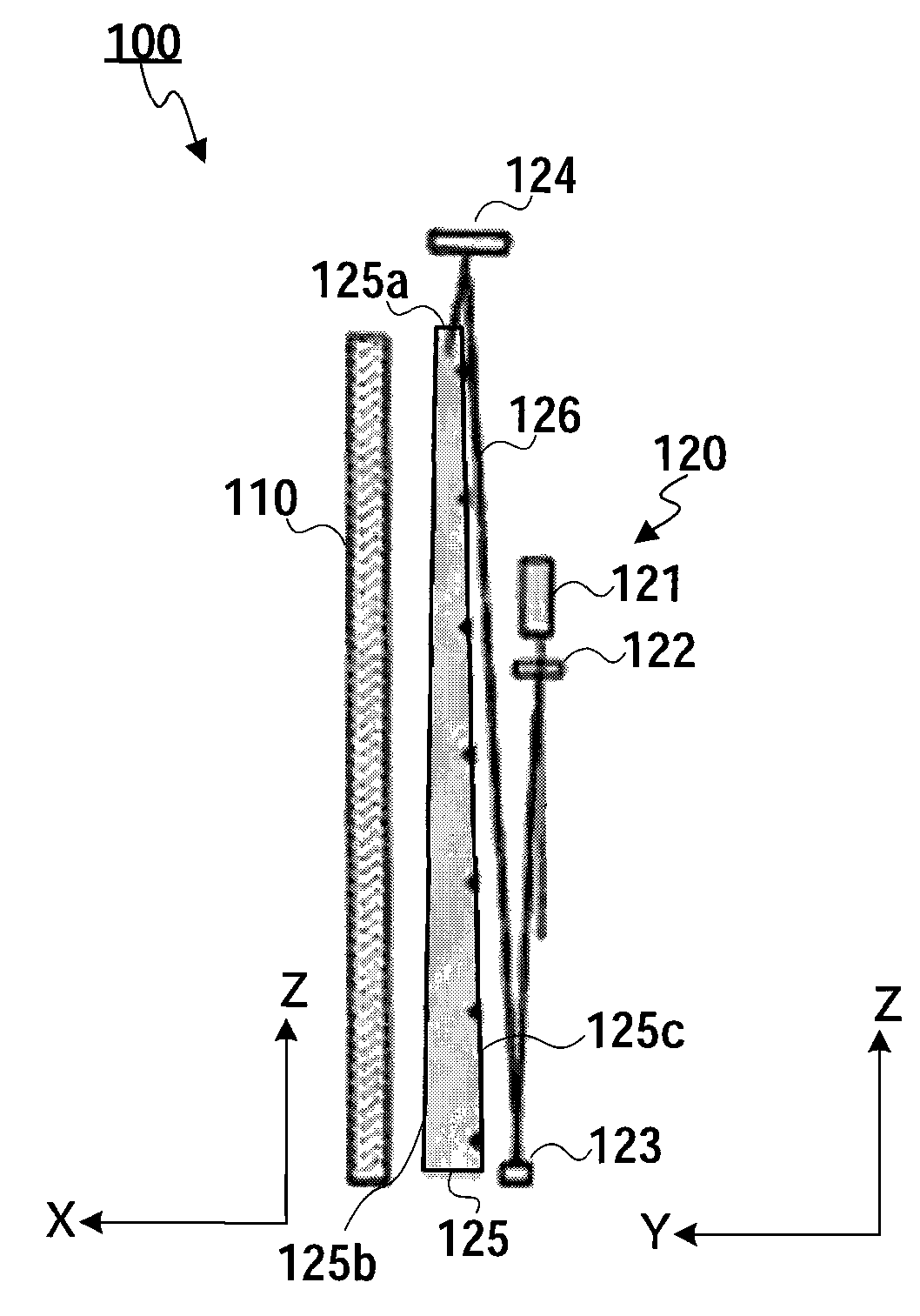
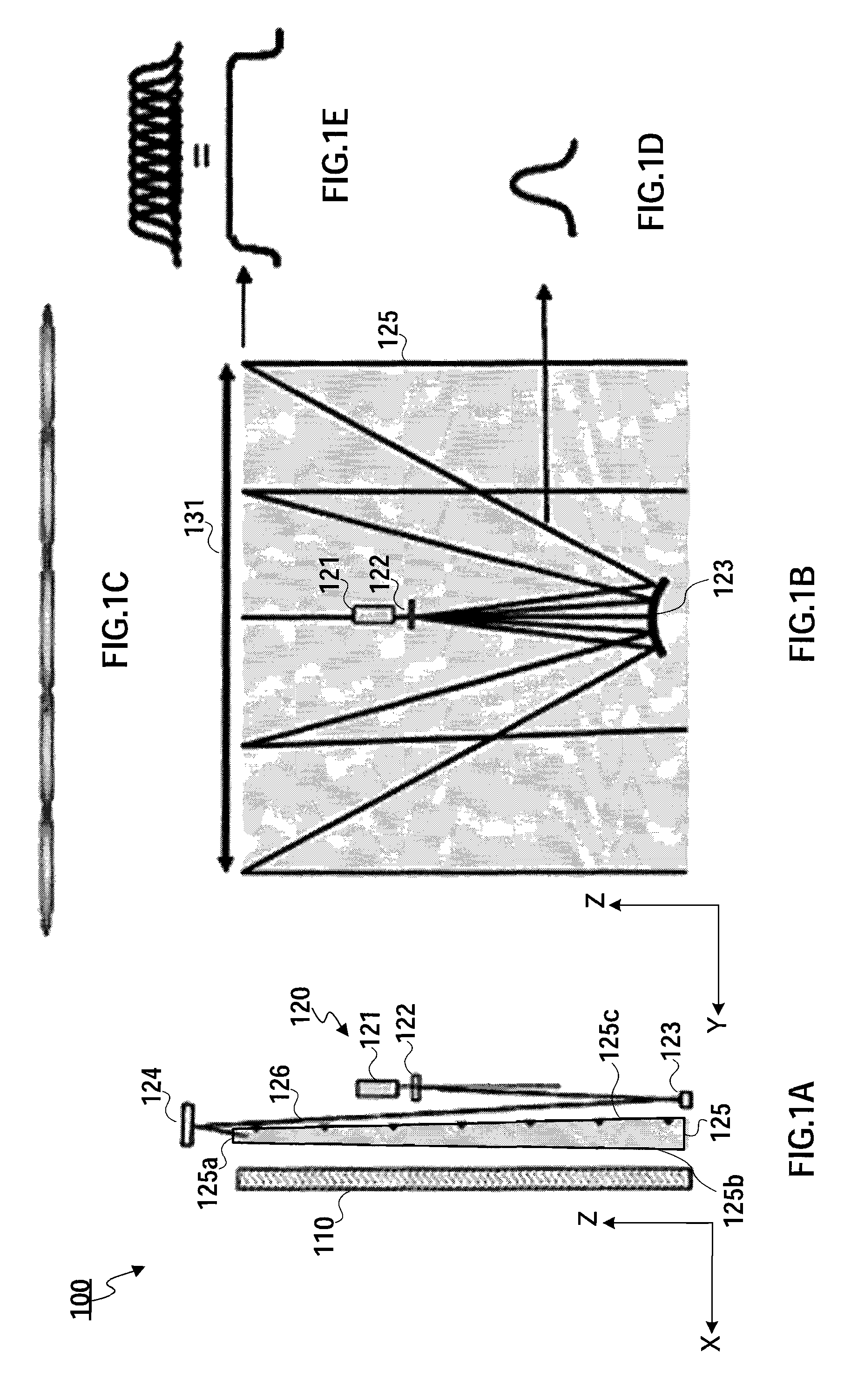
[0040]FIGS. 1A-1E illustrate a schematic layout of a back-lit panel using laser light and principle of incoherent beam shaping for uniform illumination of back panel (light guide plate). For clarity, only a few beams are represented in these figures. These figures are not to scale, with exaggerated features.

[0041]More specifically, FIG. 1A is a block diagram illustrating a schematic structure of a flat panel display including a surface light emitting apparatus according to one embodiment of the present invention; FIG. 1B is a schematic diagram for illustrating the principle of laser beam shaping according to the present embodiment; FIG. 1C is a cross-sectional view of a beam after a collimating mirror; FIG. 1D is a schematic diagram illustrating a Gaussian intensity profile of one beam; and FIG. 1E is a schematic diagram illustrating a flat-top profile on target.

[0042]As shown in FIG....


PUM


Abstract

A surface light emitting apparatus capable of providing uniform illumination while efficiently using a laser light. The apparatus comprises a light source section that includes at least one light source which emits laser beam; an optical element section that includes at least one diffractive optical element section that modifies a wavefront of the laser beam emitted from the light source section by diffraction action; and an optical guiding section that guides from an incidence surface of the optical guiding section the laser beam emitted from the diffraction optical section and emits the laser beam from a radiation surface of the optical guiding section.

Description

CROSS REFERENCE TO RELATED APPLICATIONS[0001]This application claims the benefit of U.S. provisional application Ser. No. 61 / 038,264, filed on Mar. 20, 2008, which is incorporated herein by reference in its entirety.BACKGROUND OF THE INVENTION[0002]1. Field of the Invention[0003]The present invention relates to a surface light emitting apparatus emitting laser light, and more particularly, to a method for illuminating uniformly a backlight panel of a laser display by means of incoherent laser beam shaping and a refractive optics.[0004]2. Description of the Related Art[0005]In recent years the need for flat panel displays has increased, in applications such as laptop screens, cellular phones screen and other portable devices, desk-top monitors, TV, etc. With the emergence of light valve type displays (e.g. liquid crystal displays (LCDs)) as one of the leader technologies in the flat panel industry, efforts are being made on improving backlighting: emitters as well as lighting techniq...

Claims


Application Information

Patent Timeline
Patent Type & Authority Patents(United States)
IPC IPC(8): F21V7/04
CPCG02B6/0023G02B6/0031G02B6/0066G02B27/0944G02B6/0038G02B6/0046G02F1/133621
Inventor LIU, XINBINGMILLIEZ, JANET
Owner GK BRIDGE 1
Learn More