
Card edge connector

a card edge and connector technology, applied in the direction of connection contact member material, two-part coupling device, connection device connection, etc., can solve the problem of increasing the crosstalk between increasing the signal transmission speed, and risk of causing a problem of an increase in crosstalk with adjacent signal line contacts, etc. problems, to achieve the effect of reducing crosstalk, suppressing noise, and better shielding

Active Publication Date: 2012-05-01
YAMAICHI ELECTRONICS
View PDF19 Cites 42 Cited by
  • Summary
  • Abstract
  • Description
  • Claims
  • Application Information

AI Technical Summary

Benefits of technology

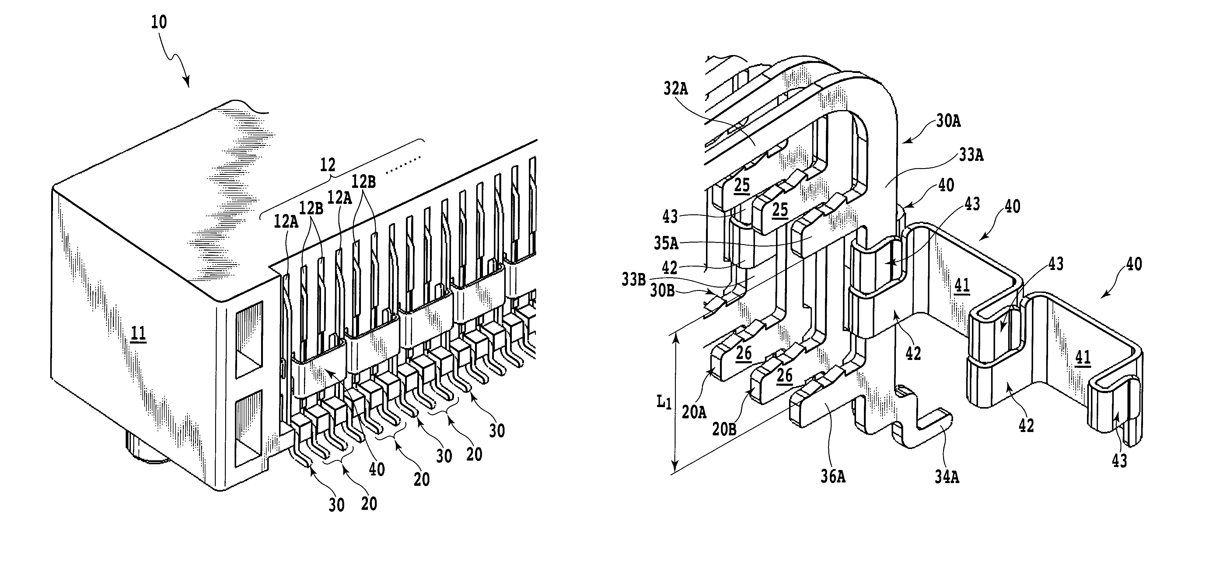
The present invention provides a card edge connector that has multiple signal line contacts and ground contacts arranged in a way that every two signal line contacts are interposed between two ground contacts. The ground contacts are electrically connected to each other by a common contact. This design creates a better shielding effect and reduces crosstalk between signals, suppresses noises, and ensures secure coupling of the ground contacts without wasting materials in the manufacturing process. The common contact has a simple structure and is easy to assemble.

Problems solved by technology

In recent years, however, crosstalk between adjacent signal line contacts has become a serious problem along with an increase in the signal transmission speed.
As a consequence, there is a risk of causing a problem of an increase in the crosstalk with an adjacent signal line contact or with a signal line contact next to the adjacent one.

Method used


Image

  • Card edge connector
  • Card edge connector
  • Card edge connector

Examples


first embodiment

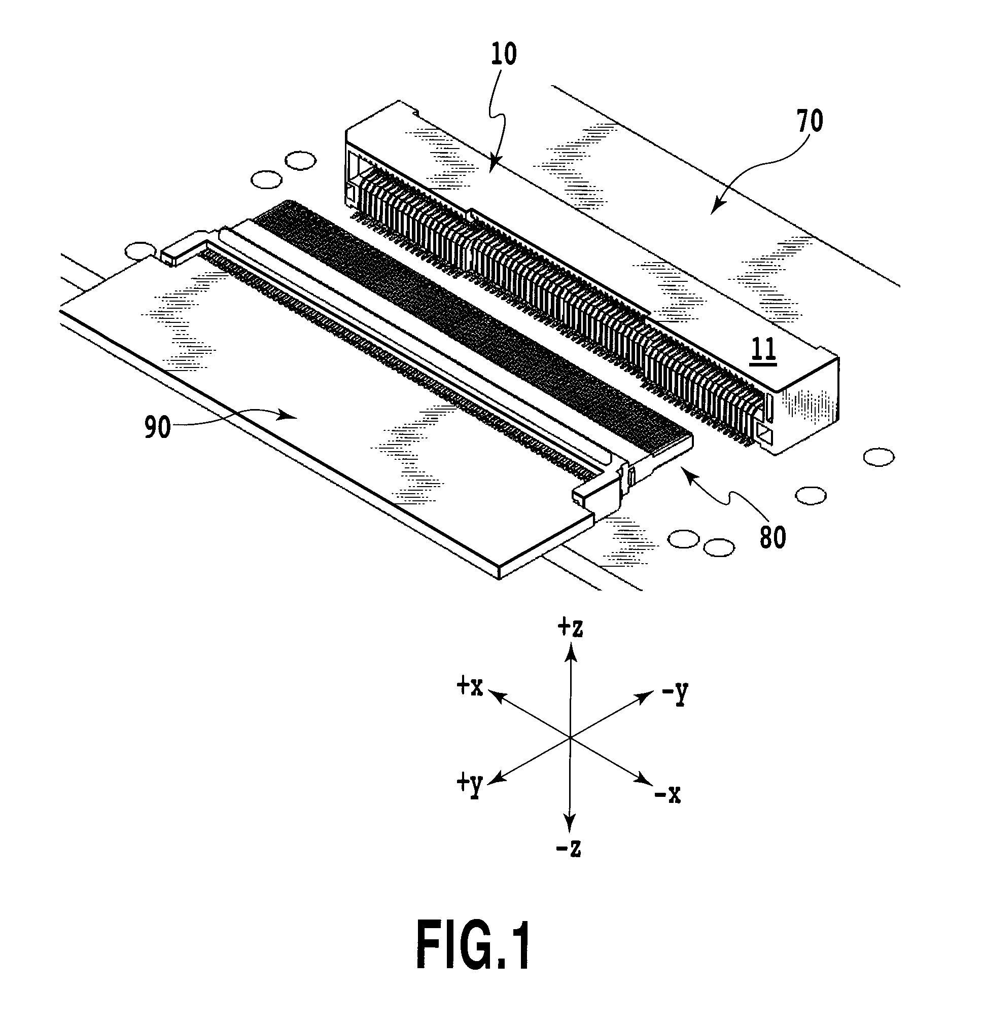
[0034]FIGS. 1 to 7 show a first embodiment of a card edge connector according to the present invention. In the description of this embodiment, it is to be noted that: “left” and “right” respectively mean a +x direction and a −x direction in FIG. 1; “front” and “back” respectively mean a +y direction and a −y direction: and “upper” and “lower” respectively mean a +z direction and a −z direction.

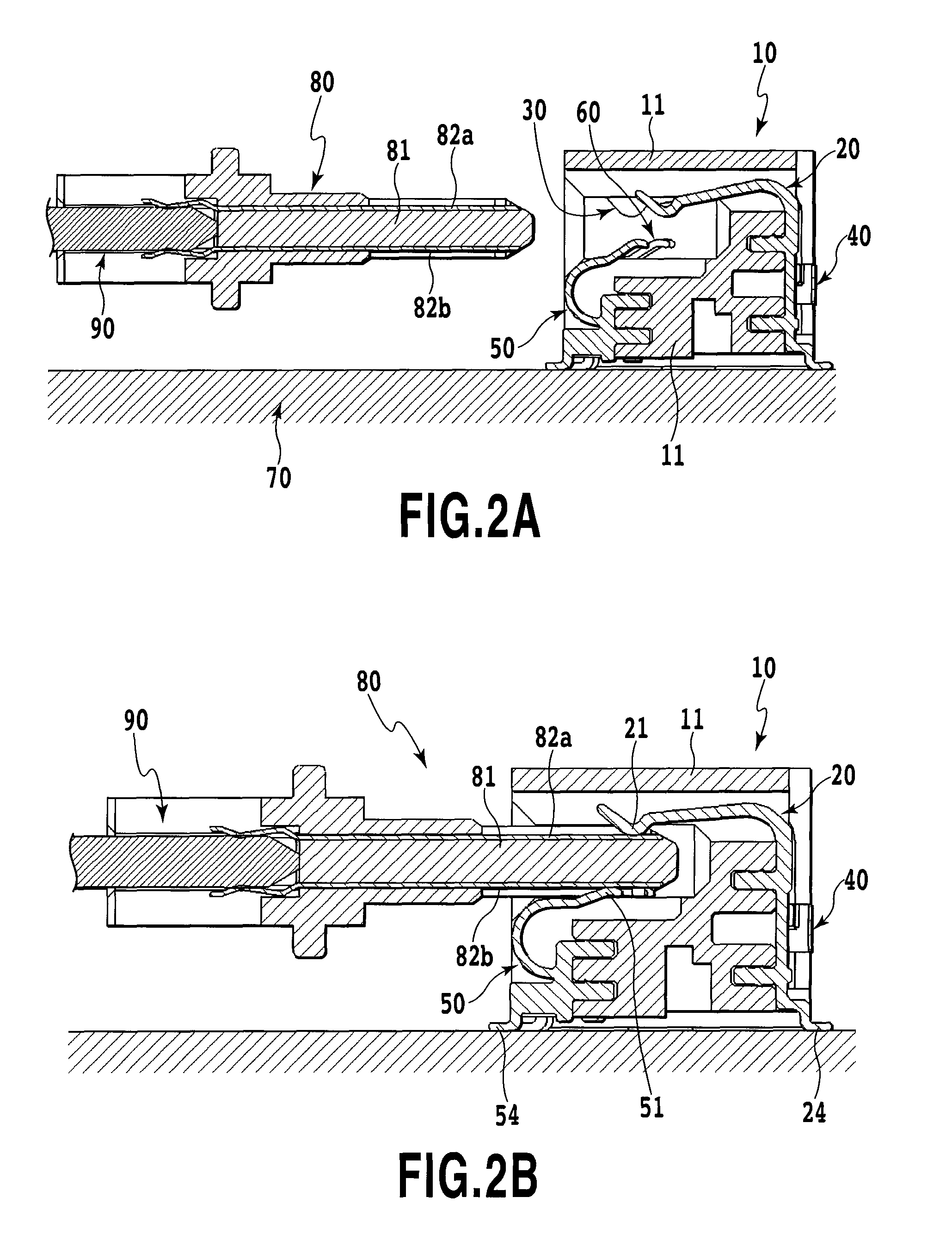
[0035]As shown in FIG. 1 to FIG. 7, a card edge connector 10 according to a first embodiment of the present invention is attached to a first printed wiring board 70. Meanwhile, a plug connector 80 to be inserted into the card edge connector 10 is attached to a second printed wiring board 90. The plug connector 80 is inserted into the card edge connector 10. Specifically, a blade 81 of the plug connector 80 is inserted into a plug connector receiving space 19a of the card edge connector 10. Accordingly, first and second pads 82a, 82b being respectively disposed on upper and lower surfaces of th...

second embodiment

[0068]FIGS. 8 to 14 show the second embodiment of the card edge connector according to the present embodiment. This embodiment is different from the above-described first embodiment in the configuration of a common contact. In conjunction with this, configurations of the first signal line contacts and the first ground contacts as well as a structure for the connection of the first ground contacts by using the common contacts are different. Hereinafter, descriptions will be provided focusing on those differences. In this embodiment as well, let us assume that signals are transmitted at a high speed only through the first signal contacts as in the case of the first embodiment.

[0069]In the description of this embodiment, it should be noted that: “left” and “right” respectively mean a +x direction and a −x direction in FIG. 8; “front” and “back” respectively mean a +y direction and a −y direction; and “upper” and “lower” respectively mean a +z direction and a −z direction.

[0070]A card e...


PUM


Abstract

The present invention provides a card edge connector as a high-speed differential signal connector configured to equalize electric potentials of ground contacts adjacent to signal line contacts, and thus to reduce crosstalk between adjacent signal line contacts. The card edge connector serves as a female connector in which multiple signal line contacts and multiple ground contacts are arranged in parallel in at least one row. In the card edge connector, the signal line contacts and the ground contacts are arranged in a way that every two signal line contacts for high-speed signals to send and return respectively therethrough are interposed between two ground contacts, and all of the multiple ground contacts arranged in the one row are electrically connected to one another by use of a common contact.

Description

[0001]This application claims the benefit of Japanese Patent Application No. 2010-019205, filed Jan. 29, 2010, which is hereby incorporated by reference herein in its entirety.BACKGROUND OF THE INVENTION[0002]1. Field of the Invention[0003]The present invention relates to a card edge connector which is a female connector provided on a printed wiring board or the like. Particularly, the present invention relates to a card edge connector provided with a crosstalk reduction structure.[0004]2. Description of the Related Art[0005]As disclosed in Japanese Patent Laid-Open No. 2007-149643, for example, a technique has heretofore been well known for electrically connecting printed wiring boards to each other by providing one of the boards with a plug connector serving as a male connector while providing the other board with a card edge connector serving as a female connector.[0006]For the purpose of suppressing crosstalk, contacts in such a connector are desirable to be arranged in a coplan...

Claims


Application Information

Patent Timeline
Patent Type & Authority Patents(United States)
IPC IPC(8): H01R4/66
CPCH01R24/38H01R12/721H01R13/6471H01R12/737H01R13/6474
Inventor ITO, TOSHIYASUKUKITA, HIROAKI
Owner YAMAICHI ELECTRONICS
Learn More