Objective lens adapter

a technology of optical adapters and lenses, applied in the field of objective lens adapters, can solve the problems of damage to the distance between the lens and the optical element, and achieve the effect of high-precision observation

Inactive Publication Date: 2012-05-01
OLYMPUS CORP
View PDF2 Cites 5 Cited by
  • Summary
  • Abstract
  • Description
  • Claims
  • Application Information

AI Technical Summary

Benefits of technology

[0007]The present invention has been conceived in light of the above-described situation, and an object thereof is to provide an objective lens adapter that makes high-precision observation possible while allowing contact between the distal end of an objective lens and an optical element without damaging the distal end of the objective lens and the optical element, even when attaching the objective lens adapter to and detaching the objective lens adapter from the distal end of the objective lens.
[0010]According to the above-described aspect, by fixing the fixed member to the lens tube while keeping the optical element in contact with the distal-end surface of the objective lens, in a state in which the elastic force of the elastic member is generated, the distal-end member is pulled in a direction close to the fixed member by the elastic force of the elastic member; and thus the state in which the optical element is in contact with the distal-end surface of the objective lens can be maintained. Thus, the problem of damage to the distal-end portion of the objective lens and the optical element can be prevented because the optical element and the distal-end surface of the objective lens are not brought into contact with an excessive pressing force. In addition, it is possible to bring the optical element and the distal-end surface of the objective lens reliably into contact and to precisely position the optical element with respect to the distal-end surface of the objective lens, allowing high-precision observation to be conducted.
[0012]By doing so, when observing the inside of a specimen by piercing the distal end of the objective lens into the specimen, it is possible to make it easy to pierce the specimen with the distal end of the objective lens due to the sharp portion that is inclined with respect to the optical axis, and it is possible to observe the specimen in a good condition by piercing the specimen with the objective lens without causing excessive damage.
[0016]By doing so, the reflection efficiency at the reflection surface of the prism can be improved. By providing the reflection film on the reflection surface of the prism, the reflectivity is not reduced even though the reflection surface is exposed and comes in contact with the specimen, and thus, it is possible to conduct observation with a bright image.
[0018]By doing so, the specimen does not come in contact with the reflection surface even when piercing the specimen with the distal-end member, and it is possible to totally reflect light at the reflection surface due to the air layer formed by the concave portion. The reflection efficiency improves as a result, and it is possible to conduct observation with a bright image. In addition, the optical element can be protected by covering the reflection surface of the optical element with the cover member.
[0019]According to the present invention, an advantage is afforded in that high-precision observation is made possible while allowing contact between a distal end of the objective lens and an optical element without damaging the distal end of the objective lens and the optical element even when attaching the objective lens adapter to the distal end of the objective lens and detaching the objective lens adapter therefrom.

Problems solved by technology

In this case, in particular, when attaching to an objective lens having a small-diameter distal-end portion in which the diameter of the distal-end portion is extremely small for piercing biological tissue such as brains, to observe an organism in vivo, there is a problem in that the distal-end of the objective lens and the optical element may be damaged if an excessive pressing force is applied to the optical element at the time of attachment.

Method used


Image

  • Objective lens adapter
  • Objective lens adapter
  • Objective lens adapter

Examples


Embodiment Construction

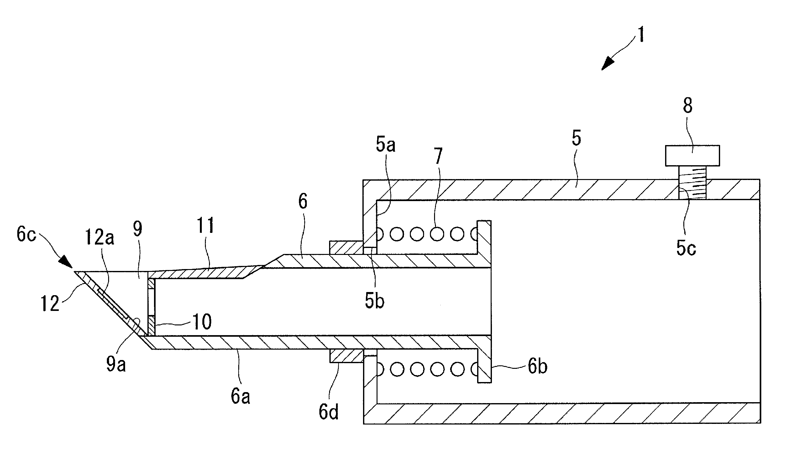
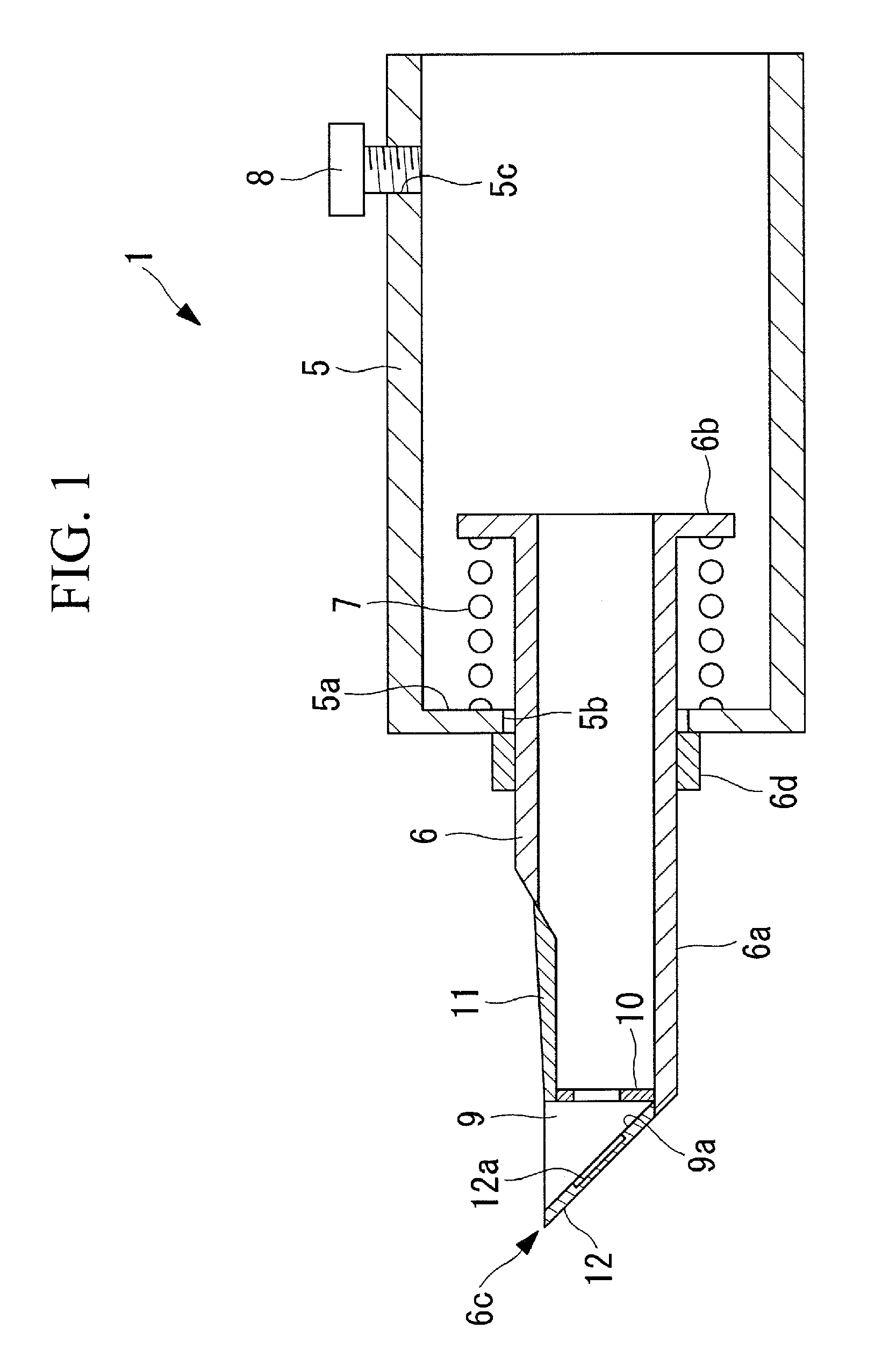
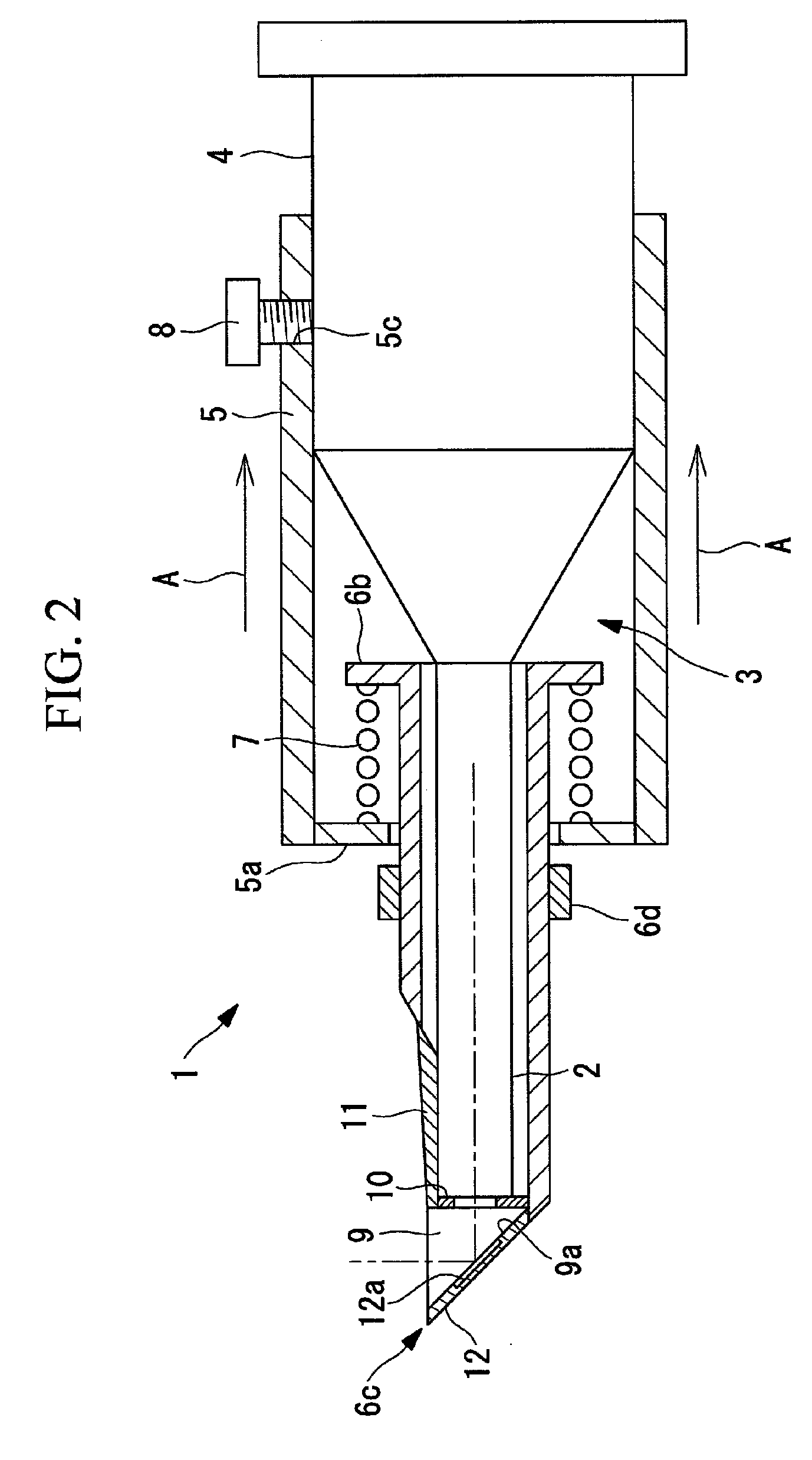
[0027]An objective lens adapter according to an embodiment of the present invention will be described below referring to FIGS. 1 to 5.

[0028]As shown in FIG. 2, an objective lens adapter 1 according to this embodiment, which is an objective lens adapter 1 that is attachably / detachably attached to an objective lens 3 for in vivo observation and that has a small-diameter distal-end portion 2, is provided with a fixed member 5 that is fixed to a lens tube 4 of the objective lens 3, a distal-end member 6 that is disposed so as to cover the small-diameter distal-end portion 2 of the objective lens 3, and a compression coil spring (elastic member) 7 that is disposed between the distal-end member 6 and the fixed member 5.

[0029]The fixed member 5 is formed substantially cylindrically, has an inside diameter that allows it to fit on the lens tube 4 of the objective lens 3, and has an inner-rib like inner flange portion 5a on one end extending radially inward. The inner flange portion 5a is pr...


PUM


Abstract

High-precision observation is made possible while allowing contact between a distal end of an objective lens and an optical element without damaging the distal end of the objective lens and the optical element even when attaching to and detaching from the distal end of the objective lens. Provided is an objective lens adapter including a fixed member that is fixed to a lens tube of an objective lens, a distal-end member including an optical element that is made to be placed in contact with the distal-end surface of the objective lens, and an elastic member that is disposed between the distal-end member and the fixed member and that urges the optical element in a direction that causes the optical element to contact the distal-end surface of the objective lens.

Description

BACKGROUND OF THE INVENTION[0001]1. Field of the Invention[0002]The present invention relates to an objective lens adapter that is attachably / detachably attached to the distal end of an objective lens to protect a front lens of the objective lens.[0003]This application is based on Japanese Patent Application No. 2008-164638, the content of which is incorporated herein by reference.[0004]2. Description of Related Art[0005]Conventionally, an adapter that is attachably / detachably attached to the distal end of an endoscope insertion unit has been known. By attaching this adapter, the field of view can be changed (for example, refer to Japanese Unexamined Patent Application, Publication No. Sho 56-85324).[0006]However, when attaching an adapter to the distal end of an objective lens in a microscope apparatus for conducting high-precision observation of a minute specimen at a high magnification, it is necessary to bring an optical element into contact with the distal end of the objective ...

Claims


Application Information

Patent Timeline
Patent Type & Authority Patents(United States)
IPC IPC(8): G02B7/02
CPCA61B1/00096A61B1/00101A61B1/00177A61B1/04A61B1/05G02B23/24G02B23/2423A61B1/0615
Inventor HIRATA, TADASHIFUKUYAMA, HIROYA
Owner OLYMPUS CORP
Why Eureka
Try Eureka