Laser microscope
a laser microscope and microscope technology, applied in the field of laser microscopes, can solve the problems of large system, complicated mechanism, and use of even larger system, and achieve the effect of high-precision observation and simple configuration
- Summary
- Abstract
- Description
- Claims
- Application Information
AI Technical Summary
Benefits of technology
Problems solved by technology
Method used
Image
Examples
first embodiment
[0032]A laser microscope 1 according to the present invention will be described below with reference to FIGS. 1 and 2.
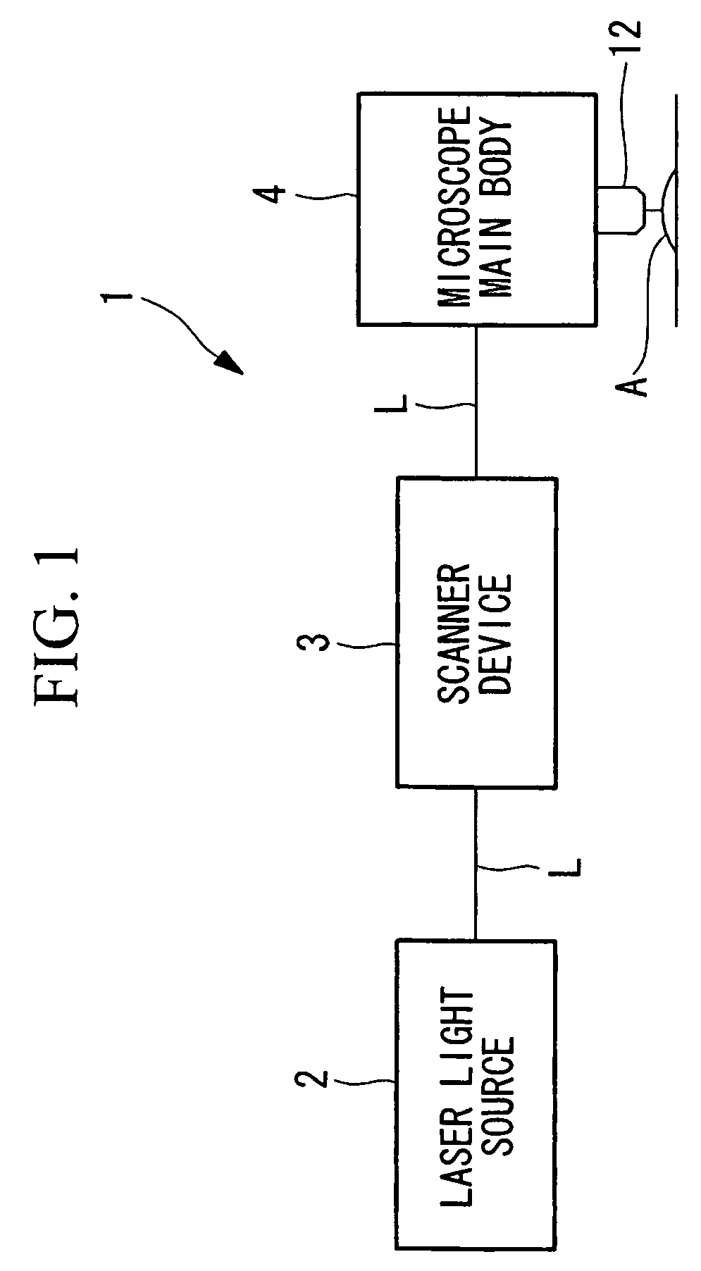
[0033]As shown in FIG. 1, the laser microscope 1 according to this embodiment includes a laser light source (light source) 2 that generates femtosecond-pulse laser light (ultrashort-pulse laser light) L, a scanner device 3 that scans the femtosecond-pulse laser light L emitted from the laser light source 2, and a microscope main body 4 that irradiates a specimen A with the femtosecond-pulse laser light L scanned by the scanner device 3 and detects fluorescence.
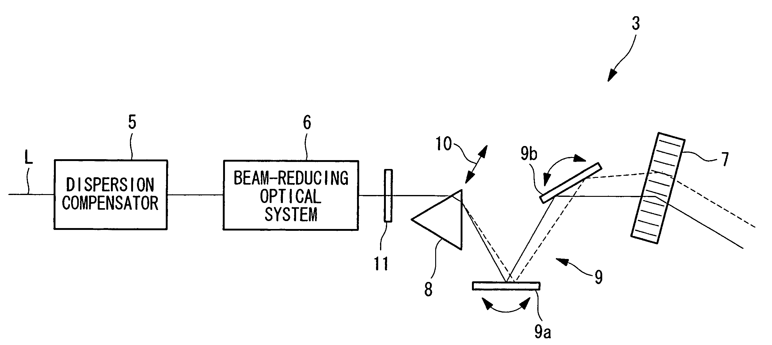
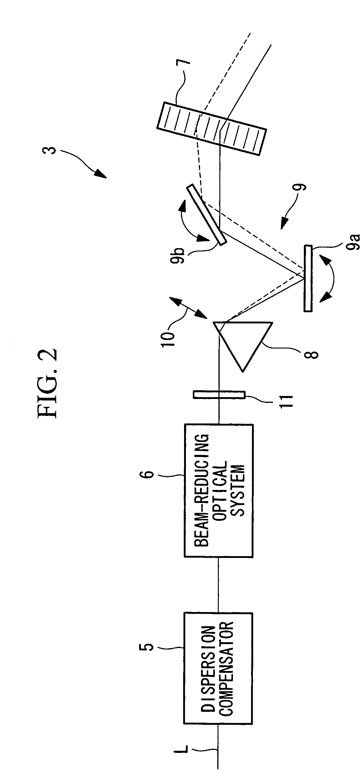
[0034]As shown in FIG. 2, the scanner device 3 includes a dispersion compensator 5 that roughly compensates the group-velocity-delay dispersion generated in the light paths of the femtosecond-pulse laser light L emitted from the laser light source 2 in the entire laser microscope 1, a beam-reducing optical system (beam-shaping optical system) 6 that adjusts the beam diameter of the femtosecond-pulse laser light...
second embodiment
[0056]Next, a laser microscope according to the present invention will be described below with reference to FIG. 3.
[0057]In the description of this embodiment, parts having the same configuration as those in the laser microscope according to the first embodiment described above are assigned the same reference numerals, and a description thereof will be omitted.
[0058]As shown in FIG. 3, the laser microscope 1 according to this embodiment includes a dispersion-compensating optical system 18, composed of static mirrors 15 and 16 and a reflection grating (angular-dispersion element) 17, and a variable-magnification beam-reducing optical system (beam-shaping optical system) 19, which are disposed between the laser light source 2 (see FIG. 1) and the acousto-optic deflector 7.
[0059]The dispersion-compensating optical system 18 is configured to move a slider (group-velocity-delay dispersion-amount adjusting unit) 20, on which the static mirror 15 and the movable grating 17 are mounted, in ...
PUM
| Property | Measurement | Unit |
|---|---|---|
| laser microscope | aaaaa | aaaaa |
| angular dispersion | aaaaa | aaaaa |
| optical path length | aaaaa | aaaaa |
Abstract
Description
Claims
Application Information
 - R&D
- Intellectual Property
- Life Sciences
- Materials
- Tech Scout
- Unparalleled Data Quality
- Higher Quality Content
- 60% Fewer Hallucinations
Browse by: Latest US Patents, China's latest patents, Technical Efficacy Thesaurus, Application Domain, Technology Topic, Popular Technical Reports.
© 2025 PatSnap. All rights reserved.Legal|Privacy policy|Modern Slavery Act Transparency Statement|Sitemap|About US| Contact US: help@patsnap.com


