
Light receiving system for meteorological observation lidar

A technology of laser radar and meteorological observation, which is applied in radio wave measurement systems, meteorology, and measuring devices, and can solve problems such as inability to measure with high precision during the day

Pending Publication Date: 2021-05-28
EKO INSTR
View PDF3 Cites 0 Cited by
  • Summary
  • Abstract
  • Description
  • Claims
  • Application Information

AI Technical Summary

Problems solved by technology

Raman lidar for temperature measurement also generally uses laser light with a wavelength of 355nm, but similarly, sunlight becomes noise and cannot be measured with high accuracy during the daytime

Method used


Image

  • Light receiving system for meteorological observation lidar
  • Light receiving system for meteorological observation lidar
  • Light receiving system for meteorological observation lidar

Examples


Embodiment approach

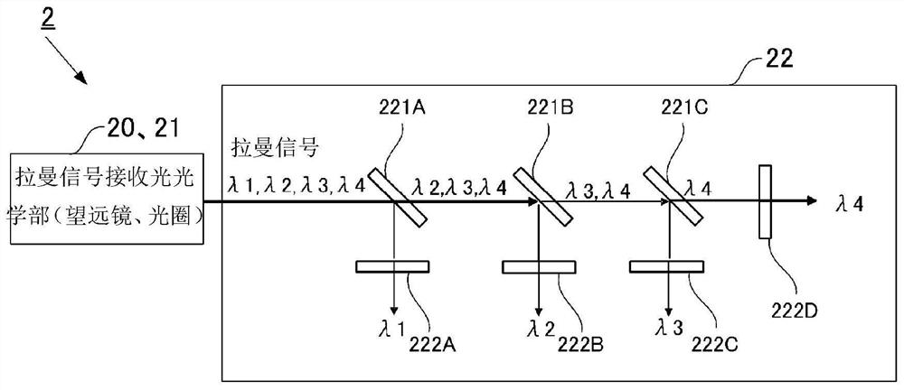
[0040] Next, use figure 2 The configuration of the receiving light system 2 for weather observation laser radar according to Embodiment 1 of the present invention will be described. figure 2 It is a schematic diagram showing the configuration of the receiving light system 2 for the weather observation lidar.

[0041] figure 2 This is a configuration example of the light-receiving system 2 for weather observation laser radar according to the present embodiment. In this example, Raman scattered light is separated and extracted using dichroic mirrors 221 ( 221A to C) and interference filters 222 ( 222A to D). In addition, in this example, as long as 222A to 222C of the interference filter 222 have a structure capable of separating wavelengths, the order can be replaced.


PUM

PropertyMeasurementUnit
widthaaaaaaaaaa
transmittivityaaaaaaaaaa

Abstract

Provided is a light receiving system for a meteorological observation LiDAR capable of radiating laser light in the UVC region (wavelength 200 to 280 nm) into the air without using a diffraction grating, and accurately observing scattered light that is generated. This light receiving system for a meteorological observation LiDAR for radiating laser light having a specific wavelength in the UVC region into the air, and observing scattered light that is generated is provided with a reflecting unit for reflecting incident light in a prescribed direction, and a spectroscopic unit for spectrally diffracting a specific wavelength from the light incident from the reflecting unit, wherein the spectroscopic unit is provided with an interference filter.

Description

technical field [0001] The invention relates to a receiving light system for a laser radar for meteorological observation. Background technique [0002] In recent years, abnormal weather such as local torrential rains has continued to occur, and it is desired to improve the accuracy of weather forecasts to predict the occurrence of abnormal weather at an early stage and to take countermeasures. It is known that in order to improve the accuracy of weather prediction, in addition to the observation of various meteorological elements on the surface and the observation of the sky using radar, the vertical distribution of air temperature, water vapor concentration, and wind direction / wind speed in the atmospheric boundary layer is observed, and this data is put into It is valid to perform calculations in weather forecasting models. [0003] A meteorological observation lidar is known as a means for measuring the vertical distribution of air temperature, water vapor concentration...

Claims


Application Information

Patent Timeline
Patent Type & Authority Applications(China)
IPC IPC(8): G01W1/00G01W1/02G01S17/95G01N21/65G01S7/481
CPCG01S17/95G01N21/65G01W1/02G01N2021/1795G01S7/4816Y02A90/10G01N2201/068
Inventor 长谷川寿一竹内荣治塚本诚矢吹正教
Owner EKO INSTR
Learn More