Wooden building element for constructing the walls of a building

a building element and building structure technology, applied in the direction of structural elements, building components, construction materials, etc., can solve the problems of high material, profiling and labor costs, and achieve the effects of convenient manufacture and introduction, advantageous functional interactions, and great economic cos

Inactive Publication Date: 2012-05-08
JUNKER HLDG
View PDF15 Cites 12 Cited by
  • Summary
  • Abstract
  • Description
  • Claims
  • Application Information

AI Technical Summary

Benefits of technology

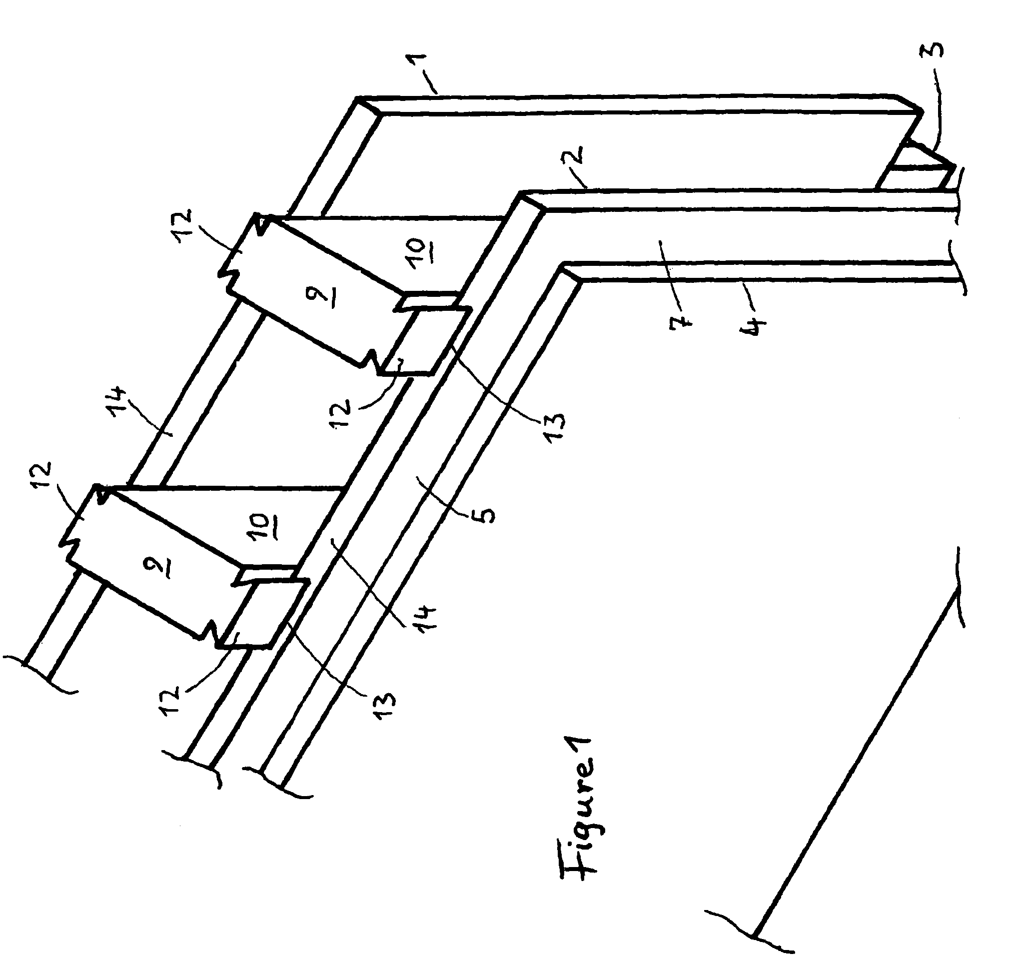
[0020]Shear forces will in any case be transmitted effectively by one wooden structural component to the neighboring wooden structural component in a direction along the building walls over the free end pieces of the grooves in the base plates of the one wooden structural component, and over the free tongue joints of the free end pieces of the supports of the neighboring wooden structural component engaging therein. For the transmission of forces, for example wind pressure in the direction normal to walls of buildings, according to wooden structural components as further developed by the invention, longitudinal edges and top edges of the base plates of the one wooden structural component are located between the sides of the longitudinal edges and top edges of wall panels of neighboring wooden structural components, as hitherto. In the further development of the known wooden structural components according to the invention, their technical and economic advantages remain completely retained and are supplemented by further technical advantages. The transmission of shear forces in the direction along a building wall of a wooden structural component onto a neighboring wooden structural component is certainly a known technical task and was already a goal being aspired towards by known technologies. For example, according to EP 0744507 B1 and in WO 97 / 39204, such shear forces in the longitudinal direction are transmitted by protrusions or points on the end of so-called module cores of a wooden structural component in connection with grooves or holes on the other ends of the same module cores of neighboring wooden structural components. These module cores are admittedly composed of several pieces and in any case can only be manufactured at great economic cost in terms of material, profiling and labor. On the other hand, according to the invention, the transmission of shear forces in the longitudinal direction takes place by supports of a wooden structural component which are very easy to manufacture and introduce, directly onto equally easily manufacturable base plates of neighboring wooden structural components. In contrast to the stated prior art, the supports and base plates and wall panels according to the invention form a surprisingly economically manufacturable combination and display particularly advantageous functional interactions of structural engineering.
[0021]In the cavities between the base plates of the wooden structural components according to the invention, without particular fixtures, individual installation channels for electricity, gas, drinking and effluent water, telecommunications or similar can certainly be built in during the construction of structures, and finally embedded in insulating materials if such installation channels are planned in due time before the erection of the structure. All the same, most installations are only planned after the erection of the structure, and must then be fixed to the outer sides of the wall panels covering the base plates, and must be covered by a further plaster wall.
[0022]In the interests of economic efficiency, the function of the wooden structural component according to the invention is also to be considered as a bearer of the conventional installations. From this there results the particular task for the further development of the invention: demarcating, in any order and without particular pre-planning, usable installations spaces in the cavity between the base plates, in such a way that structurally conventional installations are aligned without additional covering plaster walls, and can later be investigated and replaced without further ado.
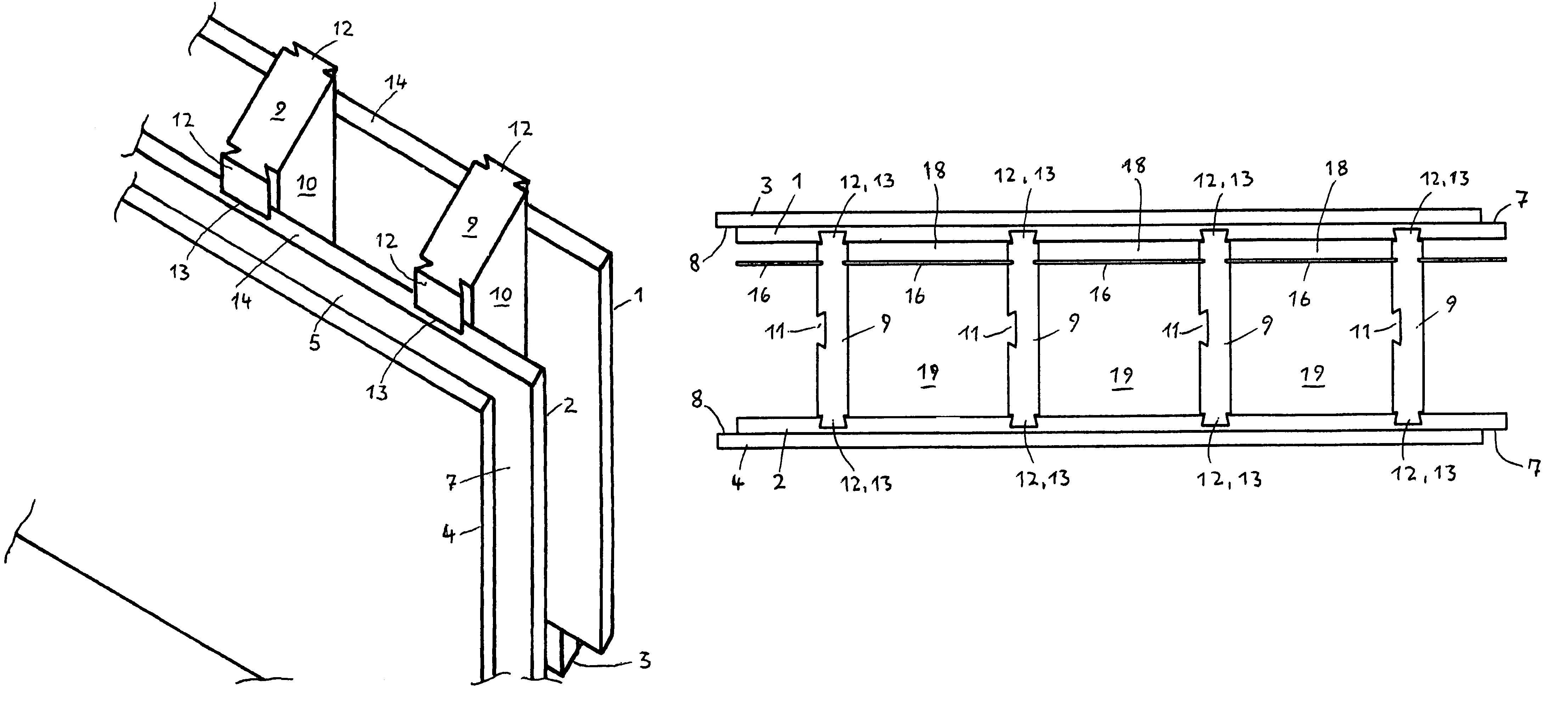
[0023]In general, the solution to the task regarding lasting installation spaces consists in aligned partition walls being introducible between the supports, roughly parallel to the base plates, which, in the finished structure, feature roughly horizontally-aligned longitudinal edges and vertically-aligned top edges, and are held on both sides along their vertical top edges by the retaining walls of the supports which are turned towards each other. These partition walls should separate installation spaces turned towards inner base plates, and wall panels with little depth, from installation spaces turned towards outer base plates and wall panels which feature a large depth. The partition walls are preferably constructed with top frames running along their top edges, which are made to engage in notches on the retaining walls of the supports. The notches on the retaining walls should have an opening width in the range from 3 to 8 millimeters, in order to incorporate the top edges of partition walls made of wood fiberboard. Moreover, they should advantageously feature a gap of 20 to 30 millimeters, preferably from 20 to 25 millimeters, from an inner base plate, and a gap of 150 to 250 millimeters, preferably roughly 200 millimeters, from an outer base plate.

Problems solved by technology

These module cores are admittedly composed of several pieces and in any case can only be manufactured at great economic cost in terms of material, profiling and labor.

Method used


Image

  • Wooden building element for constructing the walls of a building
  • Wooden building element for constructing the walls of a building
  • Wooden building element for constructing the walls of a building

Examples


Embodiment Construction

[0034]The same and similar constituents of the wooden structural component according to the invention and of the corner structural component are provided with the same labels in all the figures of the drawings, and are described together in the following description for all the embodiment types schematically represented in the drawings.

[0035]The wooden structural elements depicted in FIGS. 1 to 5 feature two base plates 1 and 2, which are constructed rectangular with roughly the same area, aligned roughly parallel to each other, and arranged with a distance between them and in a projection normal to their main surfaces, overlapping each other. Rectangular wall panels 3 and 4, of equal area, overlapping each other and in a projection normal to their main surfaces, are each fixed to one of the outer main surfaces of the base plates. The wall panels feature main surfaces which are either the same size as or slightly smaller than the main surfaces of the base plates. On the finished str...


PUM


Abstract

A wooden building element for producing planar constructions, especially for constructing the upright walls of a building. Also, a corner building element adapted to the wooden building element and to a building constructed using the elements. The wooden building elements have two approximately rectangular support bases and two wall panels that are approximately equal in area. The support bases are maintained at a distance from each other by a plurality of supports that are aligned vertically in relation to the finished building and that delimit an interior compartment for the insertion of insulating material and building installations. The wall panels are fastened to the outer surfaces of the support bases and are set off therefrom in relation to longitudinal edges that are aligned approximately horizontally to the finished building and high edges that are aligned approximately vertically.

Description

[0001]This is a national stage of PCT / EP06 / 008324 filed Aug. 24, 2006 and published in German.FIELD OF THE INVENTION[0002]The invention concerns a wooden structural component for manufacturing flat structures, in particular for the construction of upright walls of buildings[0003]with rectangular base plates of roughly equal area, arranged roughly parallel to each other, which are held, overlapping and projected normal to their main surfaces, by intermediate members at a distance from each other, and between which cover a cavity,[0004]with rectangular wall panels of roughly equal area, arranged roughly parallel to each other, which are fastened, overlapping and projected normal to their main surfaces, on the outside of the base plates, and are roughly the same size as, or slightly smaller than, the base plates,[0005]such that both the base plates and the wall panels on the finished structure are arranged horizontally, longitudinal edges roughly parallel to each other, and arranged ro...

Claims


Application Information

Patent Timeline
Patent Type & Authority Patents(United States)
IPC IPC(8): E04B2/10E04B2/08E04B2/46E04B2/48
CPCE04C2/12E04C2/34E04B1/10E04B2/54E04B2002/0206E04C1/397E04C2/36
Inventor JUNKER, DIETER
Owner JUNKER HLDG
Why Eureka
Try Eureka