Foundation adapter system

a technology of adapter system and foundation, which is applied in the direction of machine supports, cabin floor fastening, transportation items, etc., can solve the problems of affecting the installation of equipment, requiring a large effort, and many equipment installed during upgrades or reconfigurations are no longer designed specifically for shipboard applications, so as to achieve the effect of facilitating reconfiguration and greater flexibility in spotting equipmen

Inactive Publication Date: 2012-05-08
KAZAK COMPOSITES
View PDF8 Cites 16 Cited by
  • Summary
  • Abstract
  • Description
  • Claims
  • Application Information

AI Technical Summary

Benefits of technology

[0006]The present invention provides a lightweight, low-cost, easily reconfigurable foundation adapter system for providing greater flexibility in spotting equipment on a tiedown system, an array or grid of tiedown points, on a support surface such as a floor or wall. The foundation adapter system provides a plurality of adapter modules that each supports a portion of a piece of equipment. For example, using a tiedown system of parallel tracks, four modules can be used to support four corners of a cabinet. The cabinet can be oriented at an angle to the tracks, and can be supported at points between the tracks.
[0010]The foundation adapter system provides an increased load capacity to accommodate shock environments. The foundation adapter system also is simple, has a minimal number of parts, and is easy to install, with one level of attachment fittings for the equipment. The hardware is accessible for mounting the foundation adapter system to the tiedown system, and access to the tiedown system is unrestricted. One or several sizes of adapter modules can be used, each of which is securable to the tiedown system. The adapter modules add only a minimal height increase to the equipment. The adapter system is particularly suitable for accommodating shipboard COTS equipment to the standard foundation interface SMART Track mounting system.

Problems solved by technology

Much of the equipment being installed aboard ships during upgrades or reconfigurations is, however, no longer designed specifically for shipboard applications.
Thus, the appropriate mechanical, electrical, and human interfaces must be reconciled, which can require a large effort.
The necessity for adapters of various kinds has, however, several adverse effects upon the equipment installation.
The increased installed equipment height associated with the multiple adapters changes seating, keyboarding, and viewing parameters from the original equipment design, which can cause ergonomic problems for those using the equipment.
In addition, the adapters are complex, and considerable labor can be required to make the several levels of bolted attachments required from some arbitrary equipment base down to the foundation beams.
Where equipment and furniture are closely packed in a compartment, it may be necessary to remove several pieces in order to access the adapter attachment bolts for the piece being added, removed, or modified, which can increase the costs of outfitting or retrofitting compartments with equipment.

Method used


Image

  • Foundation adapter system
  • Foundation adapter system
  • Foundation adapter system

Examples


Embodiment Construction

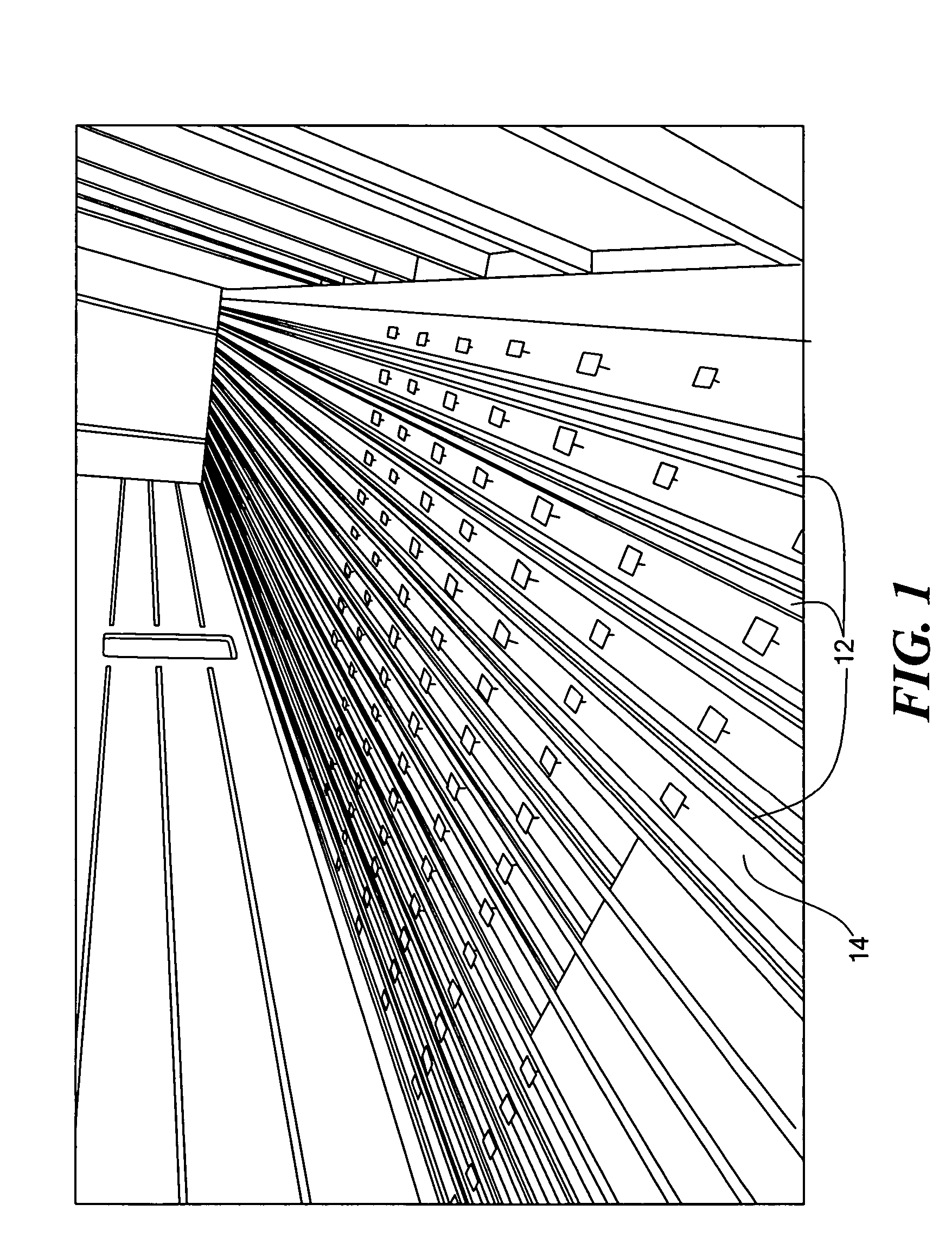
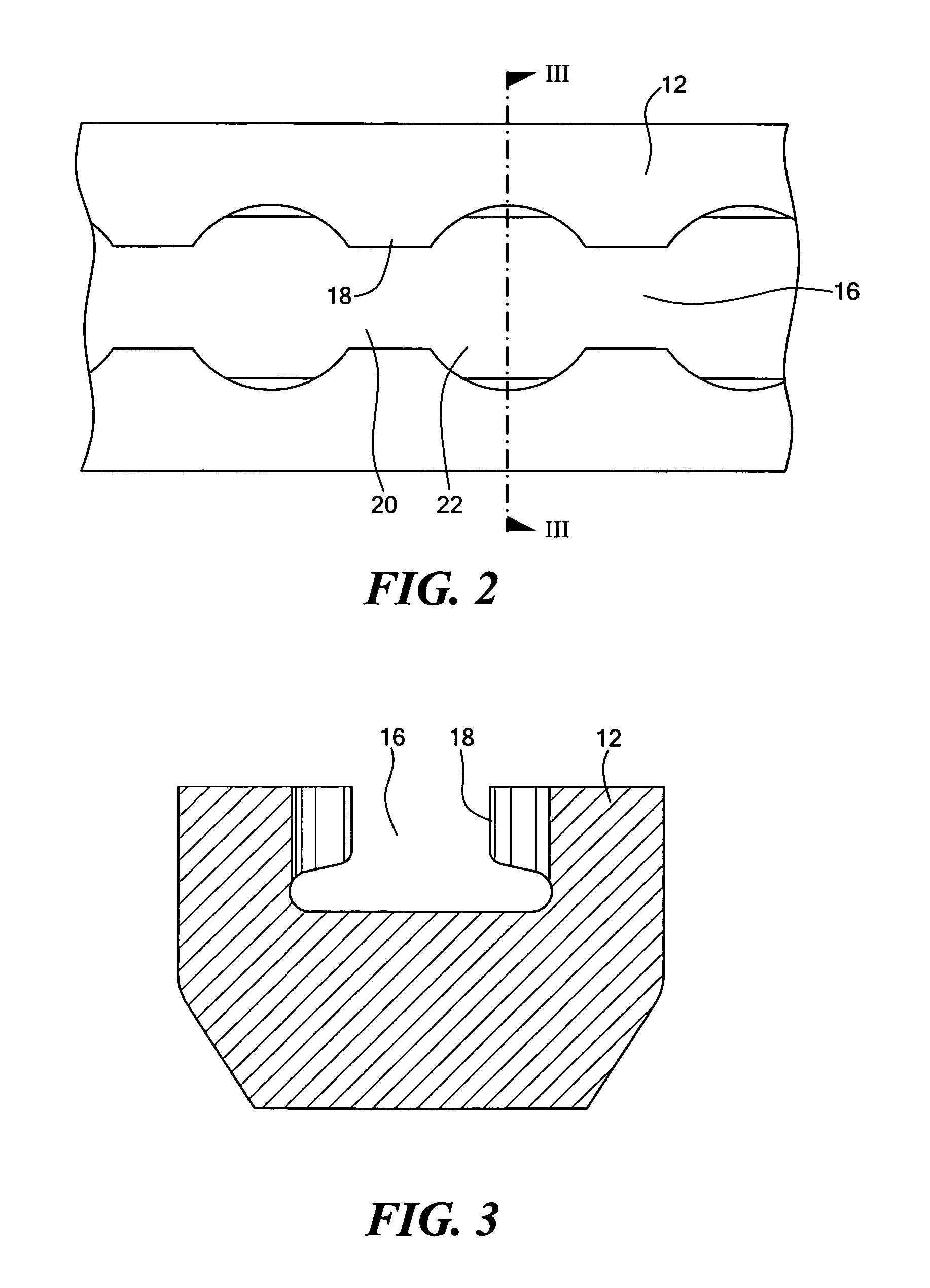
[0045]FIG. 1 shows one form of tiedown system having a plurality of tracks or rails 12 installed over a floor or deck 14. The tracks are parallel to each other and spaced equidistantly. The tracks have attachment or tiedown points at determined intervals, such as every one inch. Referring to FIGS. 2 and 3, for the SMART track system, a slot 16 is formed the length of each track 12. A lip or flange 18 is formed along the opposite upper edges of the slot to provide narrow or necked portions 20 alternating with wide portions 22 at a one-inch pitch. The narrow portions 20 constitute attachment or tiedown points, as described further below. Each COTS piece of equipment is fitted with a structural foundation 17, 19. See FIGS. 28 and 29. Four tiedown points are located at the corners of the foundation. The foundation may be of any size and can accommodate any size piece of equipment.

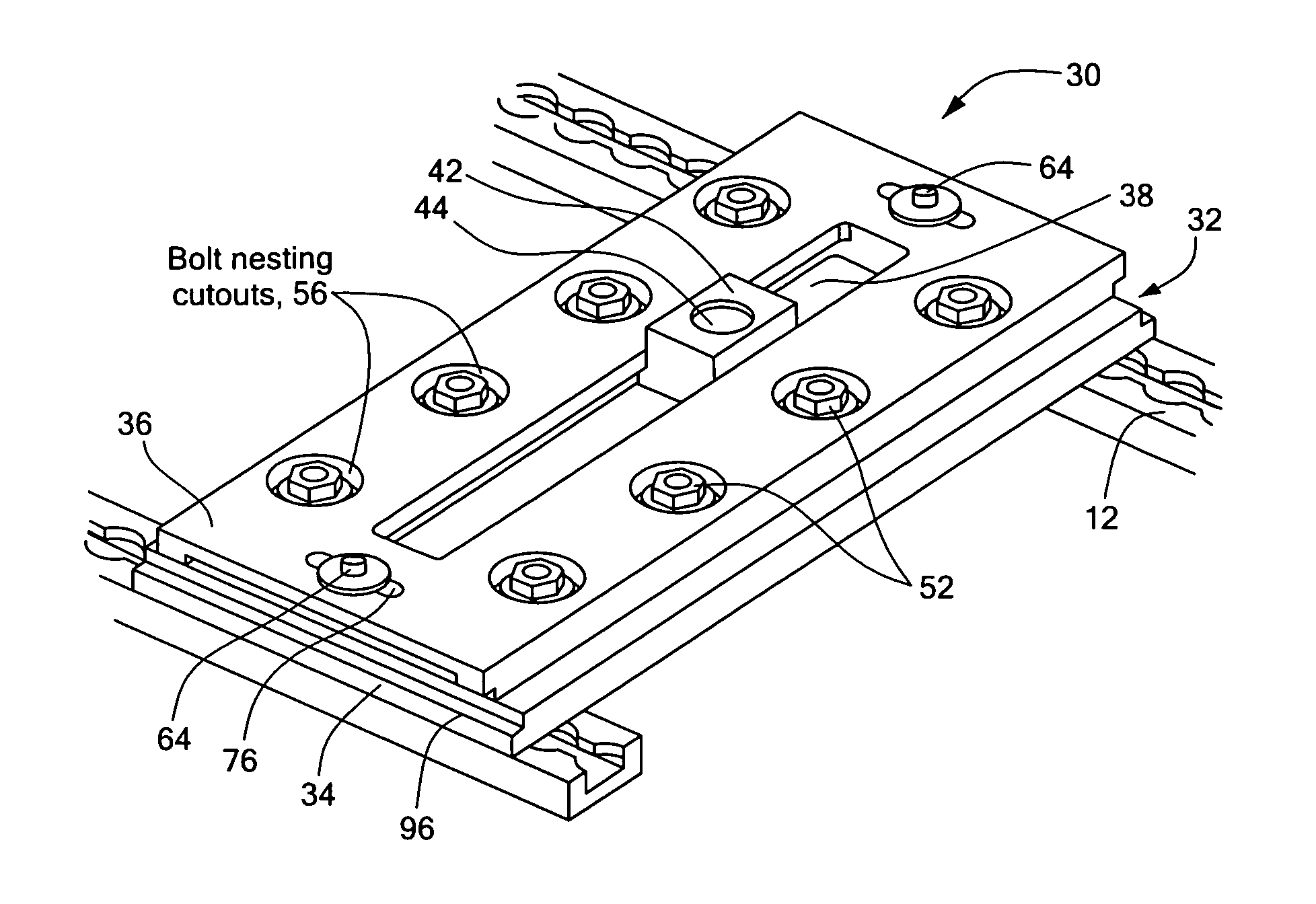
[0046]Referring to FIG. 4, an adapter module 30 of a foundation adapter system of the present invention incl...


PUM


Abstract

A tiedown system foundation adapter system provides greater flexibility in spotting equipment on a support surface. An adapter module includes a plate assembly that drops into a slotted track system and is slid along the track system until it fits into an attachment point that restrains the plate assembly from vertical pullout and motion transverse to the track. The plate assembly is then locked into position to restrain it from further translation along the track. An equipment fitting is translatably mounted with respect to the upper surface and attaches to a complementary attachment fitting on the bottom of a piece of equipment. By locating a number of modules in desired locations along the tracks and locating the equipment fitting in each module, a piece of equipment can be oriented in virtually any position and location in the space to be furnished. A deck system for a flush floor is also provided.

Description

CROSS REFERENCE TO RELATED APPLICATIONS[0001]This application claims priority under 35 U.S.C. §119(e) of U.S. Provisional Application No. 60 / 505,019, filed on Sep. 23, 2003, the disclosure of which is incorporated by reference herein.STATEMENT REGARDING FEDERALLY SPONSORED RESEARCH OR DEVELOPMENT[0002]The work leading to the invention received support from the United States federal government under SBIR Grant, Contract Nos. N00167-02-C-0005 and N00167-03-C-0015. The federal government may have certain rights in this invention.BACKGROUND OF THE INVENTION[0003]The use of commercial off-the-shelf (COTS) electronic equipment, consoles, and other furniture or accommodations aboard ships has been increasing. Equipment on a ship may be subjected to a variety of loading conditions, including shock, and the installation of such equipment must account for this loading, generally by fixing the equipment to the ship's deck. Much of the equipment being installed aboard ships during upgrades or r...

Claims


Application Information

Patent Timeline
Patent Type & Authority Patents(United States)
IPC IPC(8): F16M11/20B60P7/08
CPCB63B29/06B60P7/0815
Inventor FANUCCI, JEROME P.MCALEENAN, MICHAELPADDOCK, ANDREW F.SURVILAS, KIRK E.
Owner KAZAK COMPOSITES
Why Eureka
Try Eureka