Adjustable optical mount

a technology of optical mounts and adjustable brackets, applied in the field of optical mounts, can solve the problems of over-large, prohibitively expensive and time-consuming testing cycles, and generally not stable and repeatable in thermal cycling and vibration environment, and achieve the effect of rapid and economical construction

Active Publication Date: 2012-05-08
LENOX LASER CORP
View PDF6 Cites 13 Cited by
  • Summary
  • Abstract
  • Description
  • Claims
  • Application Information

AI Technical Summary

Benefits of technology

[0009]It is a further object of the present invention to provide an optical mount enabling adjustment and repositioning of optical elements held therein after the mount has been fixed to the supporting structure.
[0010]It is also an object of the present invention to provide an optical mount that incorporates two orthogonal-axis rotational alignment adjustments allowing a user to tilt or adjust the angle of an optical element mounted therein relative to a selected reference plane.
[0011]It is another object of the present invention to provide an optical mount that has an alignment adjustment allowing a user to rotate an optical element mounted therein relative to a selected axis.
[0013]It is a further feature of the present invention to provide a device usable in the rapid, economical construction of an optical breadboard or of a prototype instrumentation and system, and is adaptable for use with fluidic or vacuum applications, microscopy, micromachining systems, and laser technology.

Problems solved by technology

Integrated mounting hardware optimized for specific applications requires engineering design, assembly and testing cycles that may be prohibitively expensive and time consuming for all but the highest value applications.
Off-the-shelf general purpose mounts are readily available, but they are generally not stable and repeatable in an environment of thermal cycling and vibration.
Their use frequently results in overly large, cumbersome systems that are unsuited for anything but short-term laboratory feasibility studies in benign environments.
Most general purpose mounts are not amenable to such protection.

Method used


Image

  • Adjustable optical mount
  • Adjustable optical mount
  • Adjustable optical mount

Examples


Embodiment Construction

[0026]While the present invention is susceptible of embodiment in many different forms, there are shown in the drawings and will be described herein in detail specific embodiments thereof with the understanding that the present disclosure is to be considered as an exemplification of the principles of the invention and is not intended to limit the invention to the specific embodiments illustrated.

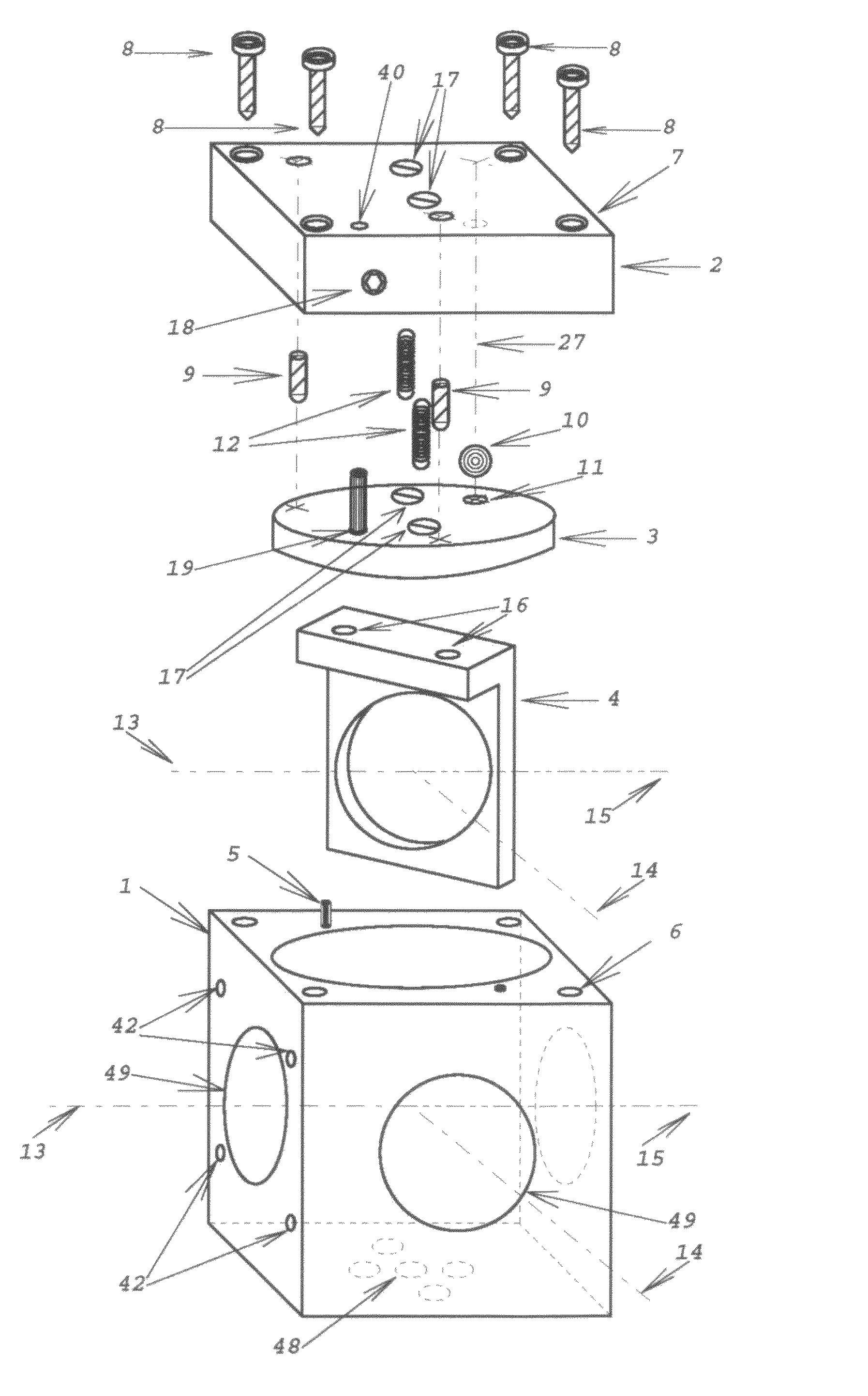
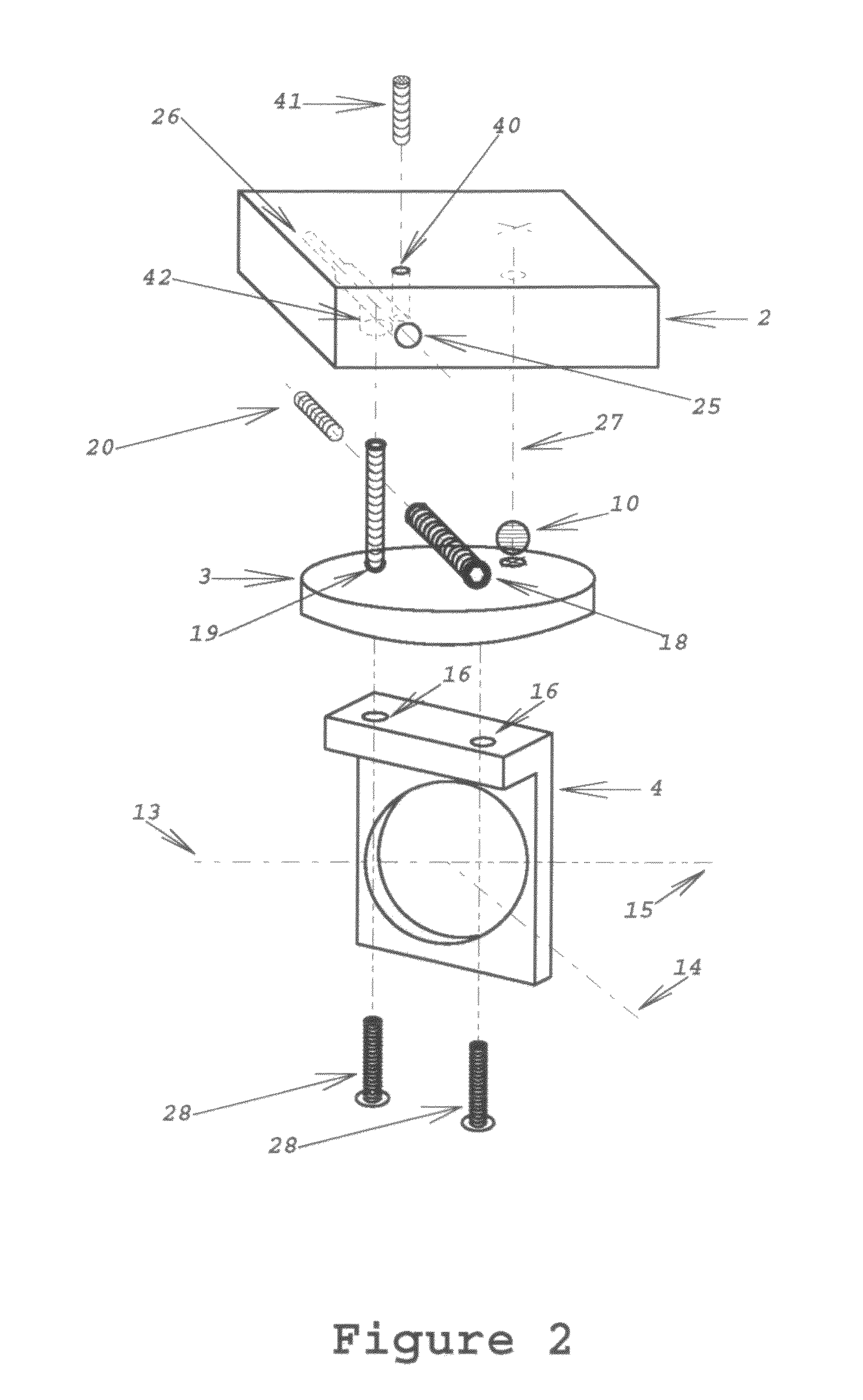
[0027]Referring to the drawings in greater detail, a mount for an optical element 21 acting upon a beam is shown in FIGS. 1 through 3. The mount is adapted for use with a table or other supporting structure (not shown) as described above generally defining a reference plane along which an optical beam will travel.

[0028]The principal components of the optical mount are a hollow body or housing 1, a gimbal base 2 mounted on top of the housing 1, a gimbal plate 3 mounted under the gimbal base 2, and an optics carrier bracket 4 fixed to the underside of the gimbal plate 3 for holding a preselect...


PUM


Abstract

An adjustable optical mount adapted for use with an optical table defining a reference plane includes a hollow housing with openings in the side walls to allow passage of an optical beam therethrough, a gimbal base fixed on the top of the housing, a gimbal plate adjustably mounted under the gimbal base, and a carrier bracket fixed to the gimbal plate for holding preselected optical elements within the housing along the path of the beam. Adjustment mechanisms are provided to tilt and rotate the gimbal plate so as to align the optical element on a selected axis relative to the reference plane.

Description

STATEMENT REGARDING FEDERALLY SPONSORED RESEARCH OR DEVELOPMENT[0001]The U.S. Government has a paid-up license in the present invention and the right in limited circumstances to require the patent owner to license others on terms as provided for by the terms of Grants #1R43NS049714-01, #9R44MH080693-02 and #5R44MH080693-03 awarded by the U.S. National Institutes of Health.BACKGROUND OF THE INVENTION[0002]1. Technical Field[0003]The present invention pertains to an optical mount and, more particularly, to an optical mount used with a supporting optical table that may be adjusted to position optical elements at selected angles relative to the table.[0004]2. Background Art[0005]Optical tables, benches, breadboards, rails, workstations and the like (herein all collectively referred to simply as tables or supporting structures) are often used for laser and other optical experiments and engineering prototypes. For example, a typical optical table has a flat upper surface with a series of ...

Claims


Application Information

Patent Timeline
Patent Type & Authority Patents(United States)
IPC IPC(8): G02B7/182
CPCG02B7/004
Inventor SOLYAR, GREGORYBLUMENFELD, WALTERD'ETREMONT, JOSEPH
Owner LENOX LASER CORP
Why Eureka
Try Eureka