Thermally conditionable light transmitting subassembly

a sub-assembly and light technology, applied in the direction of resistor details, heat exchanger elements, transportation and packaging, etc., can solve the problems of large temperature gradient between the heated perimeter and the center of the lens/window, system or device inoperative, and alter the system/device performan

Active Publication Date: 2012-05-08
MINCO PRODUCTS
View PDF11 Cites 5 Cited by
  • Summary
  • Abstract
  • Description
  • Claims
  • Application Information

AI Technical Summary

Problems solved by technology

Whether owing to natural environmental conditions (e.g., ambient atmospheric conditions with regard to use of a telescope, camera, munition guidance system, etc.) or artificial environmental conditions part and parcel of a manufacturing or industrial processes/processing (e.g., refrigerated systems wherein optical scanning is conducted or processes wherein LCD instrumentation is present), optical interference via the formation of condensate and/or ice, whether water vapor or other saturated gaseous element/compound associated with a given process/application, often times renders such systems or devices inoperative, and if not, nonetheless greatly alters system/device performance.
Due to the poor thermal-conduction properties of typical optical materials, a large temperature gradient occurs between the heated perimeter and the center of the lens/window.
As a result, such approaches are cha

Method used


Image

  • Thermally conditionable light transmitting subassembly
  • Thermally conditionable light transmitting subassembly

Examples


Embodiment Construction

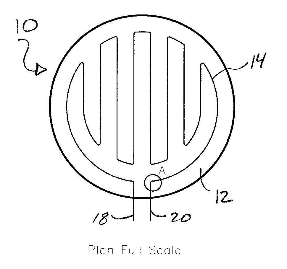
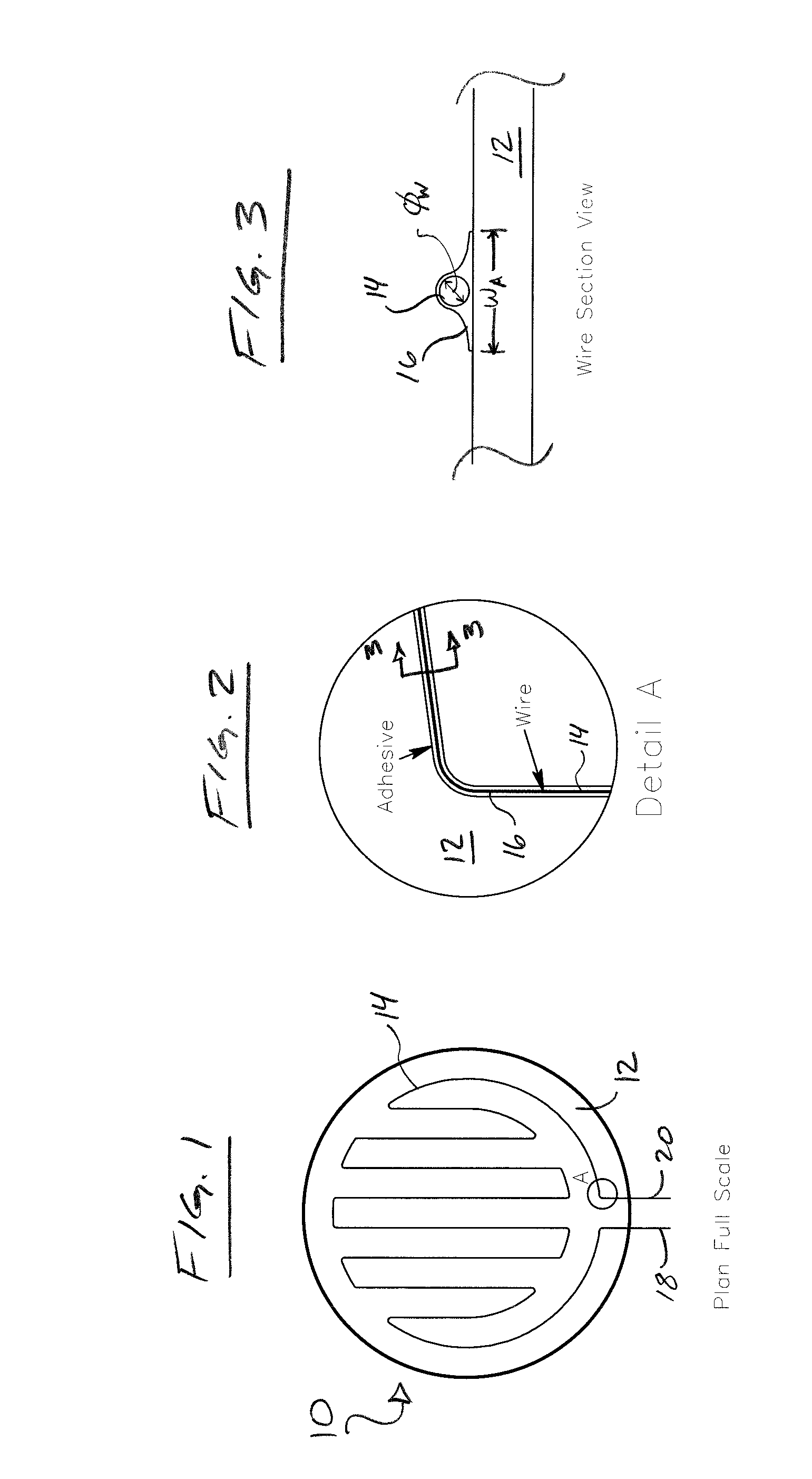
[0016]A contemplated, non-limiting representation of the article, subassembly or component of the subject invention is generally depicted in FIG. 1, with select diagrammatic details thereof provided in FIGS. 2 & 3. It is to be understood, and as should be readily appreciated, matters of size, configuration, component / material selection, etc. are dictated by functional objectives and / or performance requirements of a given application. Moreover, while the term “light” as used throughout this disclosure may have a contextual meaning in relation to visible light (i.e., the visible spectrum generally corresponding to wavelengths within a range of about 380-750 nm), it is nonetheless to be afford a broad reading and meaning, namely, the term is intended to also generally encompass electromagnetic energy or radiation beyond that associated with the visible spectrum.

[0017]With particular reference to FIG. 1, there is depicted a thermally conditionable light transmitting article 10 of the su...


PUM


Abstract

A non-film based, thermally conditionable light transmitting article is provided. The article includes an adhesively coated resistive wire and a substrate suitably selected for light transmittance. The adhesively coated resistive wire is solely and directly adhesively affixed to the substrate so as to be thereby supported upon and by the substrate. A layer of adhesive, in the form of an adhesive linkage originating from the adhesive of the adhesively coated resistive wire, is present between the resistive wire and the substrate.

Description

[0001]This is a regular application filed under 35 U.S.C. §111(a) claiming priority under 35 U.S.C. §119(e) (1), of provisional application Ser. No. 60 / 928,499 entitled “Direct Wire Bonded Thermal Element for the Prevention of Icing and Condensation in Optical Components” filed May 10, 2007, and incorporated herein by reference in its entirety.TECHNICAL FIELD[0002]The present invention generally relates to the prevention of, or recovery from, a diminished light transmission condition for an optical lens, electro-optical system, viewfinder, “window,” etc. owing to condensate formation or the like, more particularly, to a light transmitting subassembly which is thermally conditionable in furtherance of maintaining an operable, advantageous optical system functionality and / or in furtherance of preventing / remedying a diminished optical capacity condition owing to environmental / atmospheric deposition.BACKGROUND OF THE INVENTION[0003]Systems or devices wherein light (i.e., select forms / wa...

Claims


Application Information

Patent Timeline
IPC IPC(8): H05B3/06H01C1/034
CPCH01C3/12H05B3/84H05B2203/014
Inventor BOBGAN, PETER M.
Owner MINCO PRODUCTS
Why Eureka
Try Eureka