
Terminal fitting and electrical cable equipped with the same

a technology of terminal fittings and electrical cables, applied in the direction of electrical apparatus, connections effected by permanent deformation, coupling device connections, etc., can solve the problems of not being able to engage with the angled corner portions, contact resistance will become great, etc., to achieve effective restraining of core wires, enhancing the fixing force of crimp contact sections, and restraining core wires

Inactive Publication Date: 2012-05-15
SUMITOMO WIRING SYST LTD
View PDF19 Cites 39 Cited by
  • Summary
  • Abstract
  • Description
  • Claims
  • Application Information

AI Technical Summary

Benefits of technology

The terminal fitting effectively reduces contact resistance by ensuring the entire periphery of the opening edge penetrates the oxide layer, improving the electrical connection and fixing force by engaging both straight and angled edges of the core wire.

Problems solved by technology

Consequently, there is a problem that a contact resistance will become great.
However, the polygonal depressions are inevitably provided with angled corner portions.
The core wire will engages with most straight edges of the depressions upon crimping and will not be able to engage with the angled corner portions.

Method used


Image

  • Terminal fitting and electrical cable equipped with the same
  • Terminal fitting and electrical cable equipped with the same
  • Terminal fitting and electrical cable equipped with the same

Examples


first embodiment

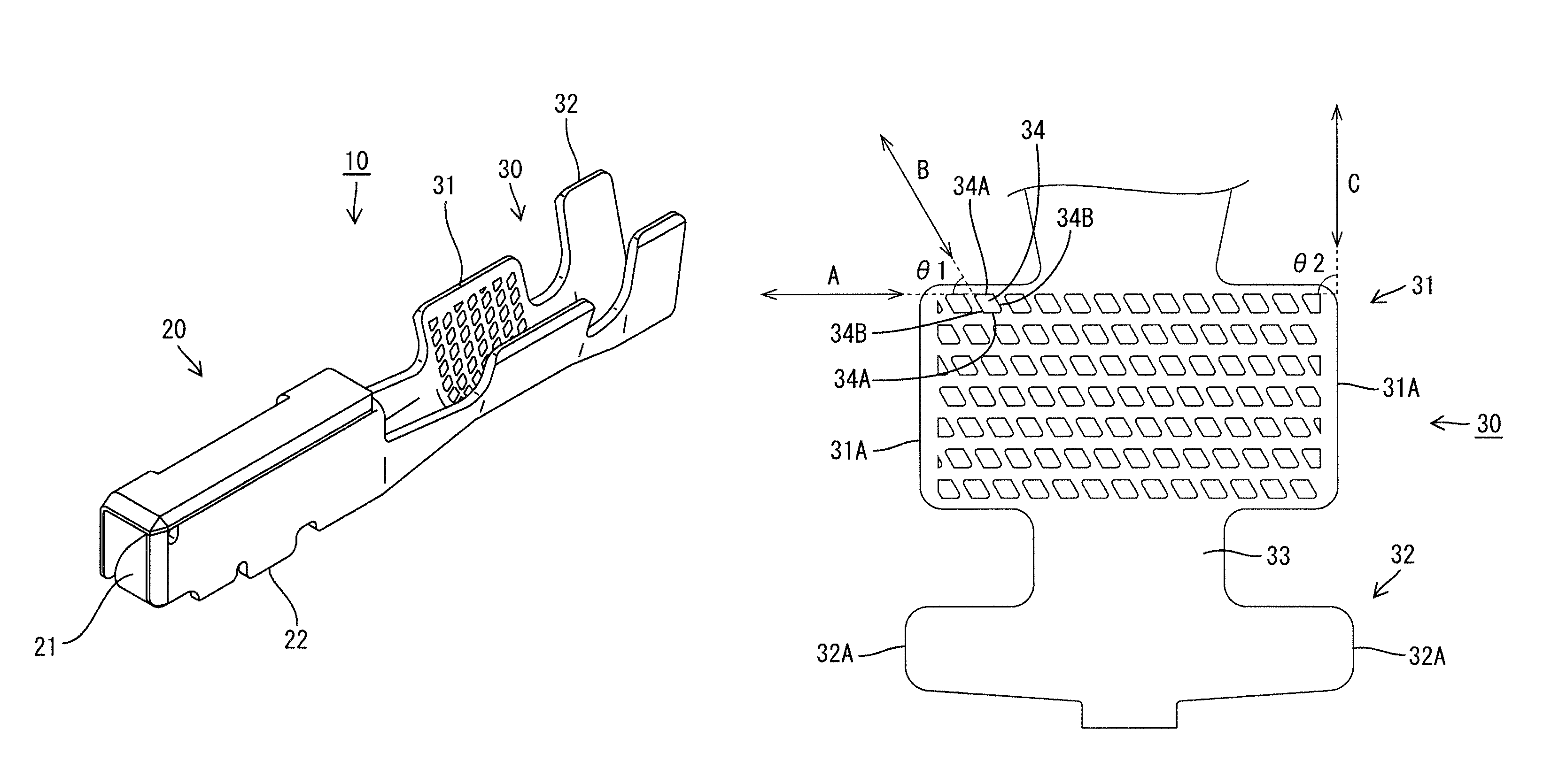
[0033]As shown in FIG. 3, the wire barrel section 31 is provided on it surface adapted to enclose an end of the core wire 42 with a plurality of serrations 34 (an example of depressions in the present invention) with which the core wire 42 engages upon crimping. Each serration 34 is formed into a polygonal recess having a substantially parallelogram opening edge. Specifically, each serration 34 includes a pair of front and rear orthogonal side portions 34A that extend in a right and left direction, and a pair of adjacent side portions 34B that are disposed adjacent to and on both sides of the orthogonal side portions 34A. The side portions 34A and 34B define a substantially parallelogram. In the first embodiment, an angle θ1 (theta one) of an extending direction (a direction shown by an arrow B in FIG. 3) of the adjacent side portions 34B with respect to an extending direction (a direction shown by an arrow A in FIG. 3) of the orthogonal side portions 34A is set to be about 60 degre...

second embodiment

[0057](4) Although the straight edges are overlapped on one another between the fourth and fifth serrations 354 and 355 in the above second embodiment, the straight edges may be overlapped on one another between the second and fifth serrations 352 and 355 in the present invention. That is, the straight edges may be arranged in the staggered manner so that the straight edges are overlapped on one another in the right and left direction.

[0058](5) Only one of corner portions of each serration may be rounded.


PUM


Abstract

A terminal fitting 10 includes a main body 20 to be coupled to a mating conductor, and a crimp contact section 30 rearward from the main body 20. The crimp contact section 30 is crimped on an end of a core wire 42 in a covered electrical cable 40 so as to surround the end. The core wire 42 includes a plurality of metallic strands 41 and is covered with a sheath 43 to form the covered electrical cable 40. Serrations 34 are provided on a contact surface of the crimp contact section 30 for surrounding the core wire 42. Each serration 34 is a polygonal shaped recess with which the core wire 42 engages upon crimping. Both diagonal corner portions 34C of each serration 34 are rounded. Thus, the whole periphery of an opening edge around the recess penetrates an oxide layer on a core wire.

Description

BACKGROUND OF THE INVENTION[0001]1. Field of the Invention[0002]This invention relates to a terminal fitting and an electrical cable equipped with the same.[0003]2. Description of the Related Art[0004]Heretofore, a terminal fitting disclosed, for example, in JP HEI 10 (1998)-125362A has been known as a terminal fitting for a wire harness of a motor vehicle. This terminal fitting includes a connecting section to be coupled to a mating conductor and a crimp contact section located in a rearward position from the connecting section so that the crimp contact section is crimped on an end of a core wire in a covered electrical cable to surround the end. If an oxide layer is formed on a surface around the core wire when crimping, an electrical connection is carried out under a condition where the oxide layer is interposed between the core wire and the crimp contact section. Consequently, there is a problem that a contact resistance will become great. Accordingly, in the prior art, a plural...

Claims


Application Information

Patent Timeline
Patent Type & Authority Patents(United States)
IPC IPC(8): H01R4/18
CPCH01R4/188H01R4/185H01R13/114
Inventor OKAMURA, KENJITABATA, MASAAKI
Owner SUMITOMO WIRING SYST LTD
Learn More