Filter assembly

a filter and assembly technology, applied in the direction of cartridge filters, dispersed particle filtration, using liquid separation agents, etc., can solve the problems of significant risk, head and body breaking apart from each other, damage to apparatus or users close to the housing, etc., to reduce simple and cheaper mechanism, the effect of reducing the likelihood of misalignmen

Active Publication Date: 2012-05-15
PARKER HANNIFIN LTD HEMEL HEMPSTEAD
View PDF29 Cites 10 Cited by
  • Summary
  • Abstract
  • Description
  • Claims
  • Application Information

AI Technical Summary

Benefits of technology

[0018]It is an advantage of the invention that the alignment of the engagement formations on the head and body parts are controlled by the keying formations. The keying formations can require alignment of the axes of the head and body parts when the head and body parts are offered to one another to assemble the housing. The keying formations can therefore reduce the likelihood of misalignment of the body and head parts, and hence of their engagement formations, during assembly. The keying formations therefore ensure that the engagement formations are properly aligned at the point the engagement formations can engage each other. Proper alignment of the engagement formations ensures that when the engagement formations are tightened by relative rotation, they engage with each other in the way they are designed so as to provide the maximum engagement between the formations. If the engagement formations are not properly aligned before they are tightened, then the engagement formations will not engage in the way they are designed to do so. For example, if the engagement formations are in the form of cooperating threads, then the threads can be crossed if they are not properly aligned before they are tightened, which will provide a sub-optimal connection. The invention can therefore be seen as separating the alignment of the axes of the head and body parts, and the connection of the head and body parts which is performed by the engagement formations.
[0019]Preferably, the keying formations are shaped and sized so as to restrict relative rotation between the head and body parts when in the initially assembly position to not more than 10° about the head and body axes, more preferably to not more than 5°, especially preferably to not more than 1°.
[0020]Once the head and body parts have been moved to the fully assembled position, the projection is no longer received in the recess and so it is possible to freely rotate the head and body parts relative to each other.
[0021]It is important that the head and body parts can be tightened by relative rotation because this can provide a simpler and cheaper mechanism for fastening the head and body parts. Other mechanisms for fastening the head and body parts include the use of components in addition to the head and body parts, such as clips, which adds to the cost of manufacture and the complication of assembly.
[0022]Preferably the keying formations are configured so that the at least one projection and at least one recess can be aligned in not more than three rotational orientations, more preferably not more than two rotational orientations, especially preferably not more than one rotational orientation.
[0023]The at least one recess can be provided by the body part. In this case, the at least one projection can be provided by the head part. Optionally, the at least one recess can be provided by the head part. In this case, the at least one projection can be provided by the body part.

Problems solved by technology

This is because if the head and body parts are not properly secured to each other, then there is a significant risk that the head and body will break away from each other due to the high internal pressures that the housing is under during operation of the filter assembly.
This can be dangerous because the head and / or body part can be forced away from the filter assembly at high velocity which can cause damage to apparatus or users close to the housing.

Method used


Image

  • Filter assembly
  • Filter assembly
  • Filter assembly

Examples


Embodiment Construction

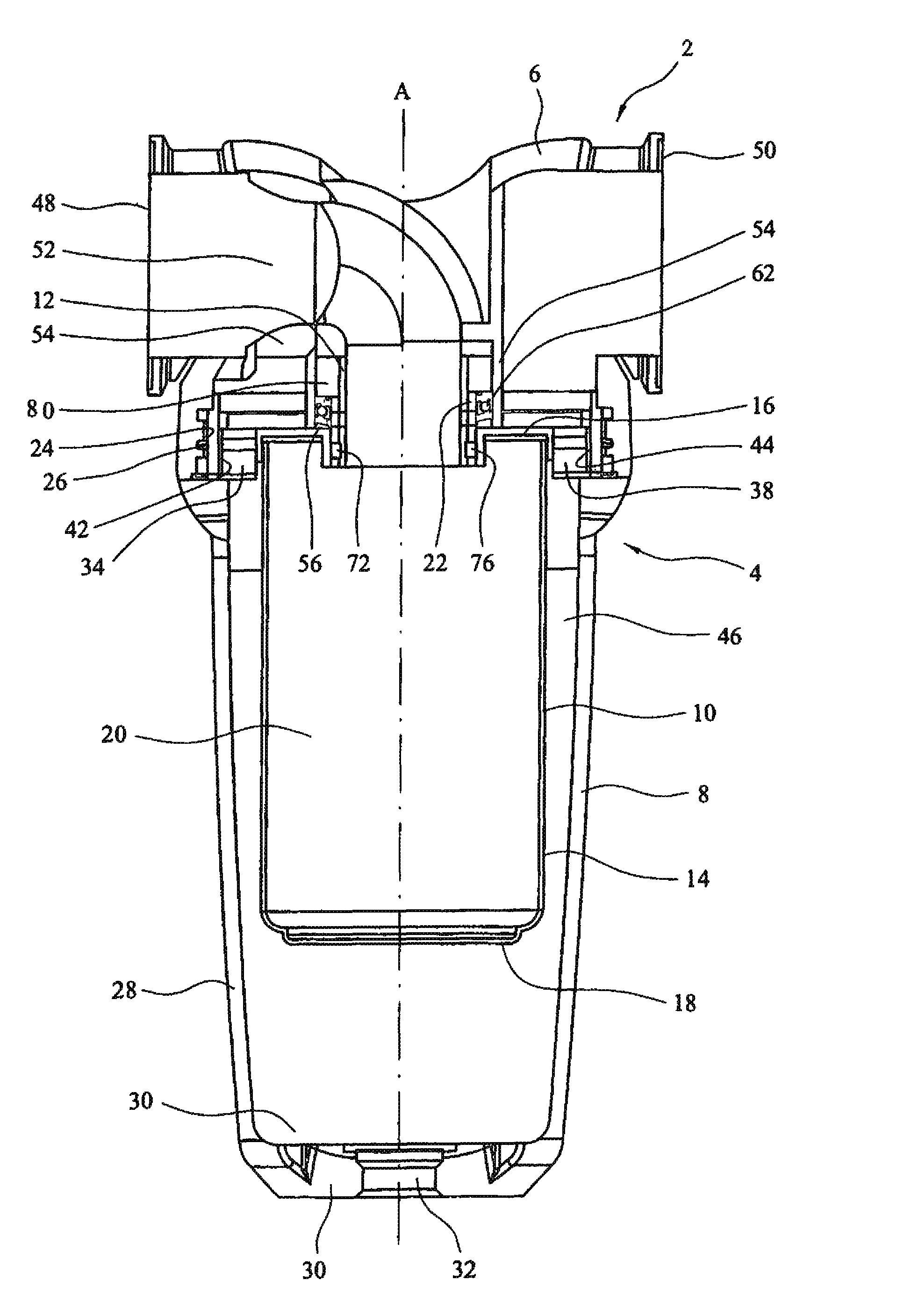
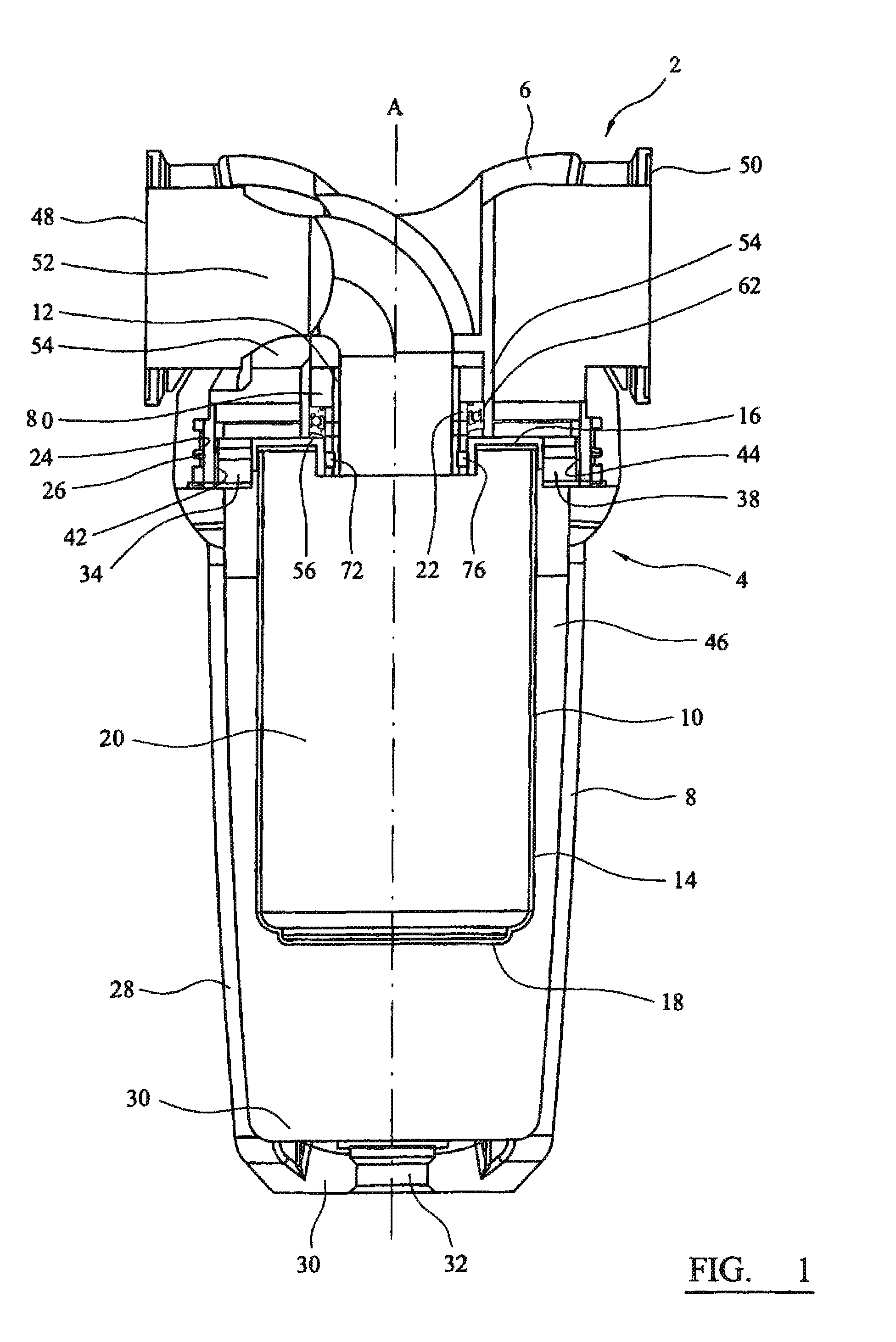
[0057]Referring to the drawings, FIG. 1 shows a filter assembly 2 which comprises a housing 4, having a head part 6 and a body part 8, a filter element 10, and a flow controller 12. The head 6 and body 8 parts each have engagement formations in the form of co-operating screw threads 24, 26 which allow the head 6 and body 8 parts to be connected to one another and separated by relative rotation about axis A. The head part 6 has a head axis and the body part 8 has a body axis, each of which are co-axial with the axis A.

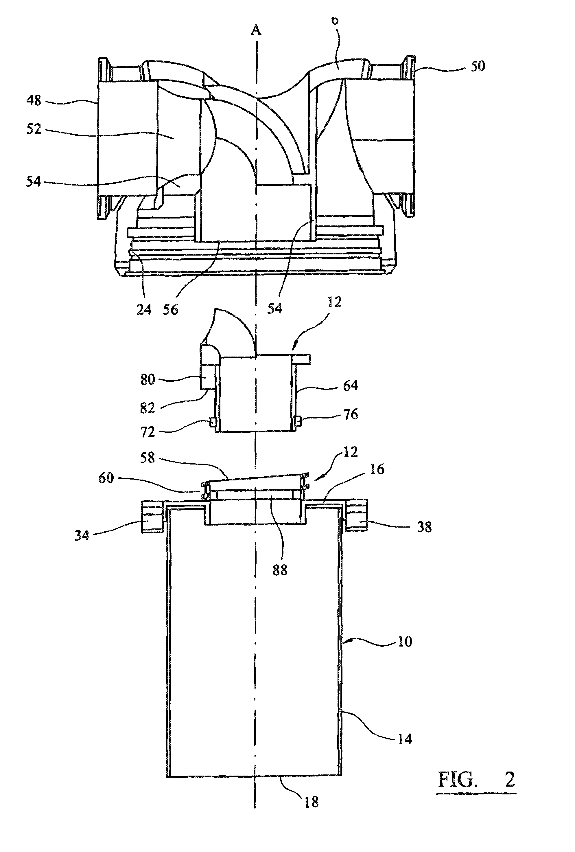
[0058]In the embodiment described, the filter element 10 is a filter element 10 which comprises a cylindrical wall section 14 formed from a filter medium, and top 16 and bottom 18 end caps. As best shown in FIGS. 2 to 4, the wall section 14 of the filter element 10 defines a hollow space 20 within it.

[0059]The top 16 and bottom 18 end caps are formed from a polymeric material. As will be understood, suitable polymeric materials include polyolefins (especially polyethyle...


PUM

PropertyMeasurementUnit
angleaaaaaaaaaa
angleaaaaaaaaaa
angleaaaaaaaaaa

Abstract

A filter assembly for removing material entrained in a fluid stream, comprises a housing for a filter element, having a head part and a body part for receiving a filter element, and inlet and outlet ports for the fluid that is to be filtered. The head part and the body part each have engagement formations which enable the head and body parts to be connected to one another and separated by relative rotation about an axis which is coaxial with a head axis and a body axis. Head and body part keying formations can be provided in the form of at least one recess which is provided in a rib on one of the head and body parts, and at least one projection which is provided on the other of the head and body parts. The keying formations require alignment of the head and body axes for initial assembly of the head and body parts when the projection is can be received in the recess in the rib so as to restrict relative rotation of the head and body parts, and so that the head and body parts can then to be moved to an assembly position in which the projection has passed through the rib so that the head and body parts can be rotated relative to each other to allow the engagement formations to become engaged to one another.

Description

CROSS REFERENCE TO RELATED APPLICATIONS[0001]This application is a continuation of co-pending International Application No. PCT / GB2008 / 002608 filed Jul. 31, 2008, which application designated the United States, and which application claims priority to Great Britain Application No. 0715269.7, filed Aug. 4, 2007, the disclosure of each of which is incorporated herein by reference.TECHNICAL FIELD[0002]This invention relates to a filter assembly for removing material that is entrained in a fluid streamBACKGROUND OF THE INVENTION[0003]Filtration of a fluid, such as a gas in a compressed gas system is generally required so that the fluid is sufficiently free of contaminants (liquid, solid or gaseous) for a subsequent application or to minimise adverse effects of contaminants on components of the system. For example, removal of compressor oil from a compressed gas stream can be required to minimise chemical contamination and accumulation on valves which might lead to malfunction of the val...

Claims


Application Information

Patent Timeline
Patent Type & Authority Patents(United States)
IPC IPC(8): B01D46/00
CPCB01D46/009B01D46/2411B01D2265/026
Inventor BITTLE, THOMAS S.LANE, BRIAN
Owner PARKER HANNIFIN LTD HEMEL HEMPSTEAD
Why Eureka
Try Eureka